
3D Printed Mold Inserts: Uses, Limits & Shot Life
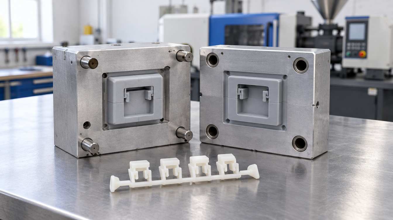
3D printed mold inserts are the core and cavity blocks of an injection mold, produced by additive manufacturing and mounted in a machined mold base or frame. The press sees an ordinary tool; only the part-forming geometry is printed. Photopolymer inserts are used to mold prototype and short-run parts in the production thermoplastic, while metal-printed inserts are used for conformal cooling and longer runs. A polymer insert's shot life depends mostly on part geometry and heat, not on the printer that made it.
This guide is based on how printed tooling behaves under clamp load, melt heat and ejection, and on the published trial reports listed under References. It covers thermoplastic injection molding on production and benchtop presses. YIDIMU doesn't publish an injection-tooling rating or shot count for any of its resins, and nothing below should be read as one.
What a printed insert actually does in the mold
In most setups the print isn't the whole mold. The inserts drop into pockets in an aluminum or steel frame, often a master unit die (MUD) style base, and the frame takes the clamp force, aligns the halves and carries the hardware. Protolabs Network describes this insert-in-frame layout as the more common and more accurate of the two standard configurations. Fully printed stand-alone molds are more prone to warping with repeated use.
That split of duties is the whole design idea. The printed insert only has to hold the cavity shape against melt pressure and heat for each shot. Anything that needs stiffness, wear resistance or a thread stays in metal: guide pins, ejector pins and fasteners. The sprue bushing stays in metal too, so the machine nozzle never seats directly on the print.
Two different technologies share the name. Photopolymer inserts from SLA, DLP, LCD masked exposure (MSLA) or PolyJet are quick to make and quick to replace, and they're the focus of this article. Metal inserts from laser powder bed fusion are production tooling. They're chosen for printed conformal cooling channels and tool life, not for lead time.
Printed insert, aluminum or silicone: which fits the job
A resin-printed insert makes sense when you need molded parts in the real polymer and the design is still changing. Once the geometry is frozen and the quantity runs into the thousands, a machined tool is usually the more predictable path.
| Option | What it's for | Molded material | Main limit | Choose it when |
|---|---|---|---|---|
| Resin-printed insert (SLA, DLP, MSLA, PolyJet) | Design checks and short runs | Production thermoplastic, within the insert's heat limit | Heat, wear, cracking, slow part cooling | The geometry will change again and you need real molded behavior |
| Metal-printed insert (laser powder bed fusion) | Conformal cooling, bridge or production tooling | Production thermoplastic | Cost, post-machining, longer lead time than a resin insert | Cycle time or cooling uniformity justifies the investment |
| Machined aluminum insert | Bridge tooling | Production thermoplastic | Machining lead time; slower to revise | The design is stable and the quantity exceeds what a printed insert reliably holds |
| Silicone mold from a printed master | Cast parts, not injection molding | Casting polyurethanes and similar | Not the production polymer or process | You need appearance or fit parts and molded behavior doesn't matter |
If the parts only need to look and fit like production parts, a silicone mold cast around a resin-printed master is often simpler than any injection tool. The injection route earns its extra effort when molded behavior matters: how the polymer fills, where weld lines land, and how a snap fit or living hinge behaves in the actual grade.
How many shots does a 3D printed mold insert last?
There's no single number. Published results run from single-digit shot counts to a few thousand. The spread comes mainly from geometry, heat and support, not from the printing process.
At the high end, a Formlabs white paper reports a polypropylene strap insert, printed in a high-temperature resin, that ran roughly 1,500 to 2,500 cycles before breaking. The same report attributes that result largely to the insert's simplicity: a flat part, a large gate, no fine features, and a metal frame around it.
At the low end, a peer-reviewed study of material-extrusion (FDM) inserts reached 15 cycles with its best design. After that, accumulated injection pressure deformed the insert and the parts began to flash at the parting line. The process is different, but the lesson is the same, and these factors decide where a given insert lands:
Melt temperature versus the insert's heat deflection temperature. The further the melt runs above what the resin tolerates, the faster the cavity surface softens, creeps or crazes.
Standing features. Thin cores, tall ribs and small pins are heated from several sides and bend under fill pressure. They usually fail long before the main cavity face.
The gate area. Melt arrives hottest and fastest there, so erosion and cracking tend to start at the gate and at the shutoff next to it.
Draft and surface texture. Every ejection drags the part along the cavity walls. Low draft or deep texture turns ejection into a repeated shear load on the print.
Filled polymers. Glass or mineral fill wears a photopolymer surface much faster than an unfilled grade does.
Heat buildup between shots. A polymer insert conducts heat poorly, so its temperature climbs over consecutive shots unless you give it time or air to cool.
That last point trips people up. If parts release cleanly at shot 5 and start sticking at shot 30, check the insert temperature before you redesign the draft.
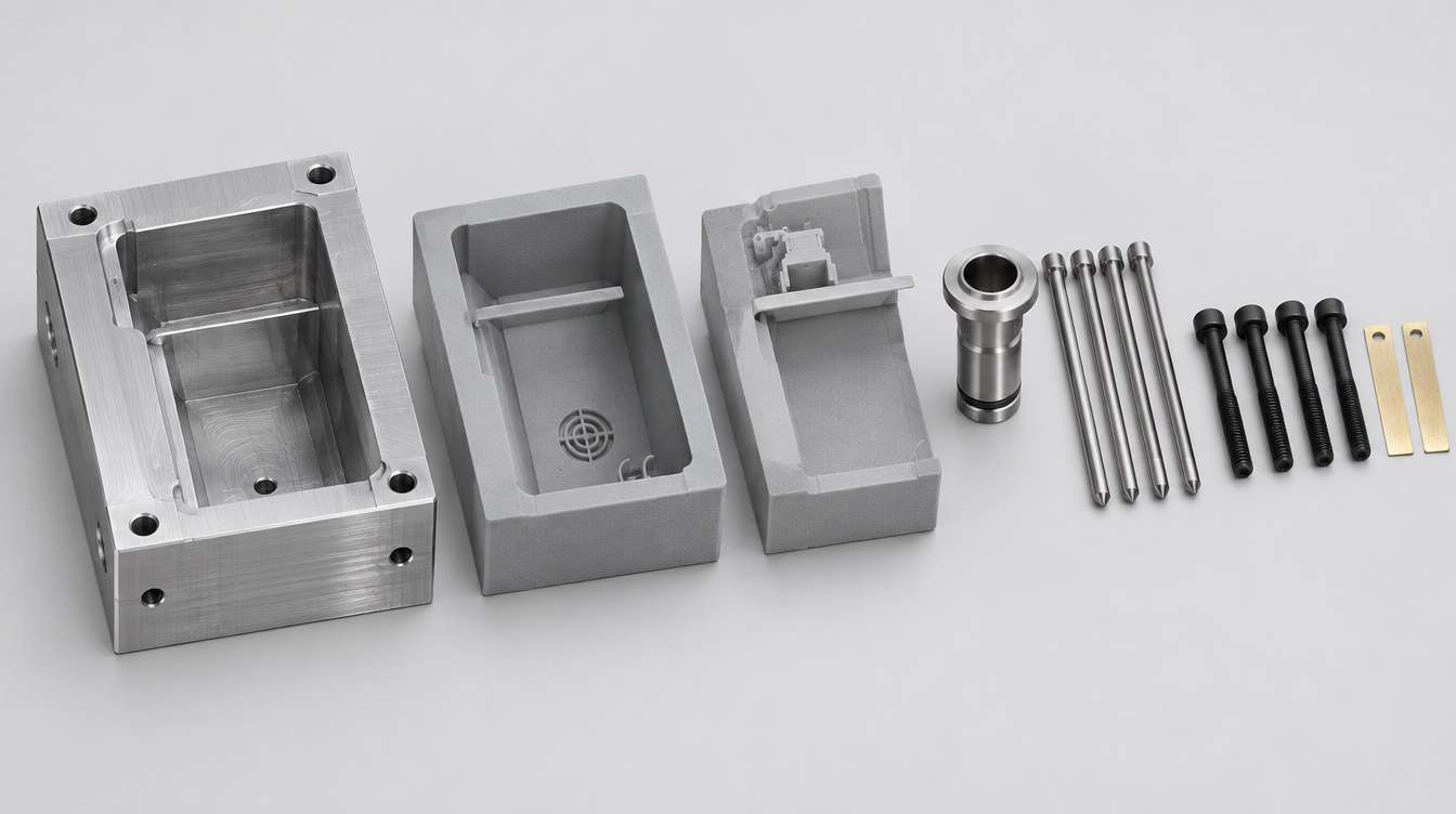
Treat shot life as a test result for one geometry, one resin and one process window. A revision that thickens a core or moves the gate often buys more life than switching to a different resin.
What a printed-insert trial can and can't tell you
A printed insert is good at exposing design problems in the molded part. It's weak evidence for final dimensions and cycle time, and those two gaps are where most misreadings of a trial come from.
Questions a printed insert answers well
Whether the part fills, and where short shots, weld lines and air traps appear
Whether the gate location and wall transitions cause visible flow problems
How snap fits, living hinges and thin walls behave in the actual polymer grade
How the part assembles with its mating components
How two candidate grades compare in the same geometry
Questions to treat with caution
Final part dimensions. Printed inserts cool the part far more slowly than steel or aluminum, which is why Stratasys's PolyJet molding guidance calls for extended cooling times. In semi-crystalline polymers such as PP, PA and POM, slower cooling can change crystallinity, shrinkage and warp. A dimension measured on a printed-insert part won't necessarily repeat on the production tool.
Mechanical properties. The FDM insert study cited above reported a lower modulus in samples molded from the printed tooling insert. If a test depends on stiffness or strength, record which tool the samples came from.
Cycle time. Cooling time on a printed insert tells you nothing useful about cycle time on a steel tool.
The insert's own deviation. The insert is a printed, post-cured part with its own dimensional deviation, and that adds to whatever the molding process does. Measure the insert, not only the molded parts.
A workable rule is to sign off geometry and function on printed-insert parts. Dimensions and the process window are then signed off on first articles from the production tool. The resin prototype to injection-molded part workflow covers where each check belongs.
From CAD to first shot
The sequence below assumes an existing frame with standard insert pockets. Detailed rules for gates, vents, draft and backing are in the mold design guide for resin-printed tooling.
Split the tool into inserts that fit your frame. Designing to a standard pocket lets one frame serve many projects. Keep the sprue, and where possible the runner, in metal.
Design for the printed material. Add draft, radius the internal corners and keep enough backing behind the cavity. Leave finishing stock on shutoffs and locating faces.
Orient and support for the molding faces. Put supports on the back and sides. A support mark left on a shutoff face becomes flash on every shot.
Wash, dry and post-cure to the resin's documentation. Some high-temperature resins specify a thermal post-cure in addition to UV. Don't shorten it to save a day.
Measure after post-cure, not after printing. Check parting-face flatness, fit in the pocket and critical cavity dimensions. Large flat inserts can move during curing, and on the press that shows up as flash on the first shot.
Fit and shim in the frame. Seat the inserts fully, shim if needed, and confirm the nozzle contacts the metal sprue bushing.
Start short and slow. Stratasys recommends a short shot at slow injection speed first, then increasing shot size until the cavity is nearly full before adjusting hold pressure. Log settings and shot count, and inspect the gate and shutoffs at fixed intervals.
One small habit pays off: put a revision code on a non-molding face of each insert. When three versions are on the bench, the trial notes stay tied to the right geometry.
Choosing the resin and the printer
The resin sets the heat and wear limit. The printer mostly determines whether you get flat, well-fitting blocks, and whether a replacement insert matches the last one.
Resin
Heat deflection temperature, with its method and load. Ask for HDT measured to ISO 75 or ASTM D648, with the load stated. A general "heat resistance" figure without a method can't be compared with another resin or with your melt temperature.
Stiffness and brittleness. Highly crosslinked, high-temperature photopolymers tend to be brittle. Sharp internal corners and thin cores are where they crack first.
Post-cure schedule and dimensional change. Know the full cure schedule, and how much the part moves during it, before you set finishing stock.
Release agent compatibility. If you'll spray a release agent, check that it doesn't soften or attack the cured surface.
Printer
The build area needs to fit the insert blocks plus finishing stock, ideally with both halves in one build. More important is whether large flat faces come off the platform flat, and whether a reprinted insert matches the original. XY pixel size doesn't answer either question. The reliable check is to print your own insert pair, post-cure it and measure it.
For photopolymer inserts, YIDIMU's industrial range includes the Eternal M1 and the larger Eternal M2, both LCD masked-exposure printers. The M2 is the one to evaluate when an insert pair, or several insert sets, need to go in one build. YIDIMU's resin range also includes a high-temperature resin. Ask for its technical data sheet, and run a staged trial on your own geometry before planning quantities.
When to stop using printed inserts
Printed inserts are a development tool with a clear end point. Move to machined or metal-printed tooling when:
You need to sign off final dimensions or a production process window
The required quantity is beyond what your trial showed the insert can hold reliably
The polymer's melt temperature or filler content is beyond what the insert resin survived in testing
Cycle time or durability of a cosmetic texture is part of the acceptance criteria
If you're weighing a printed insert for a specific part, send the part CAD, polymer grade, target quantity and frame or press details through YIDIMU's project request page. We'll review whether the insert geometry is realistic to print and what a first trial should check.
Author: [Name], [Title]. [One-line relevant experience]
Technical reviewer: [Name], [Title]
Last updated: [Date]