
01
Lattice cell geometry
Cell topology, strut layout and local density change how a structure distributes deformation. Compare geometry variants using the same evaluation method where possible.
FLEXIBLE STRUCTURES & FOOTWEAR
Flexible structures should be evaluated as a complete combination of geometry, material, printing and post-processing. The same resin can feel and behave differently when cell design, wall thickness, deformation space, orientation and final cure condition change.
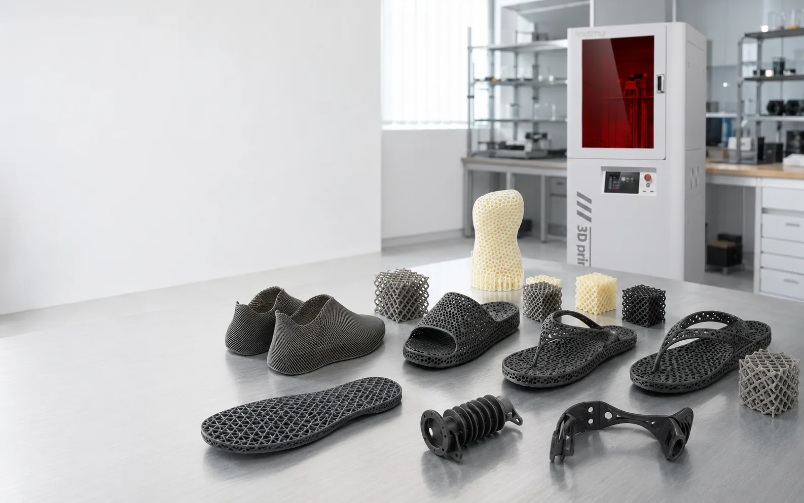
A hardness label is not a complete description of how a finished flexible part will feel, compress or deform.
Flexible photopolymer resin is a light-curing material system. It should not be treated as interchangeable with thermoplastic TPU/TPE, true silicone or silicone rubber. Material selection should follow the printer, current resin documentation and representative-part testing.
APPLICATION GALLERY
The most useful project starts with a real structure and a real evaluation target—not with a generic request for a “soft” material.
GEOMETRY CHANGES THE PART
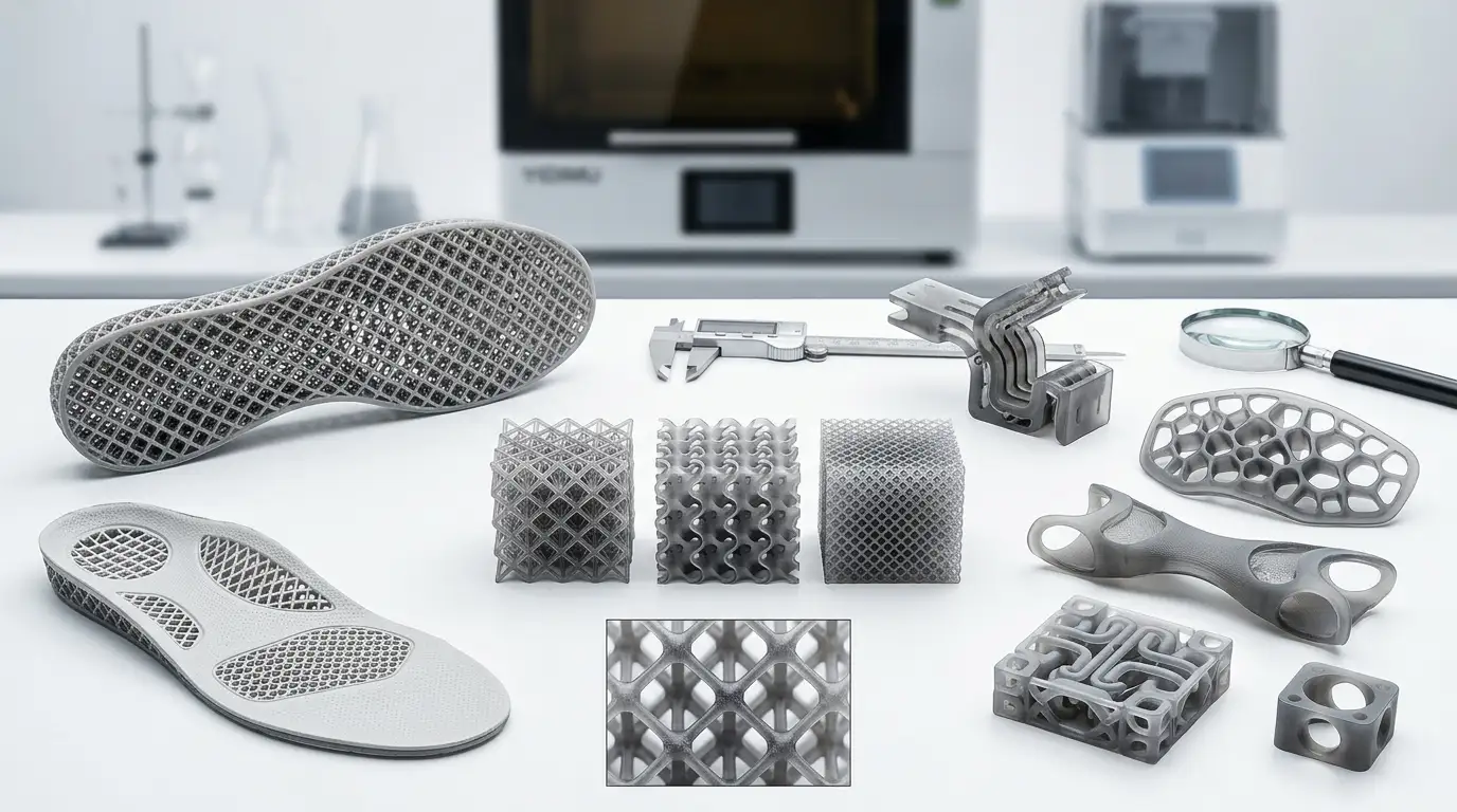
Final touch and mechanical response can change with geometry, wall thickness, lattice architecture, printing conditions and post-processing. A single material-hardness value cannot describe the finished part by itself.
Cell topology, strut layout and local density change how a structure distributes deformation. Compare geometry variants using the same evaluation method where possible.
Thin walls may flex more easily while thicker sections can add local support. Transitions between wall thicknesses also deserve inspection.
Open lattices need practical drainage and washing access. Trapped resin or inaccessible internal areas can complicate the post-processing workflow.
Reinforce mounting points, edges or load-transfer zones without automatically making the entire part thicker or denser.
Leave enough room for the intended local deformation. Adjacent walls, skins or embedded features can limit the motion a lattice was designed to provide.
Orientation changes support placement, drainage, visible surfaces and the relationship between the geometry and the printing process.
Supports should protect printability while keeping removal and finishing practical on flexible or detailed surfaces.
Evaluate the part after the required washing, complete drying and UV post-curing process. Compare parts only when the post-processing condition is controlled and documented.
COMPRESSION VALIDATION
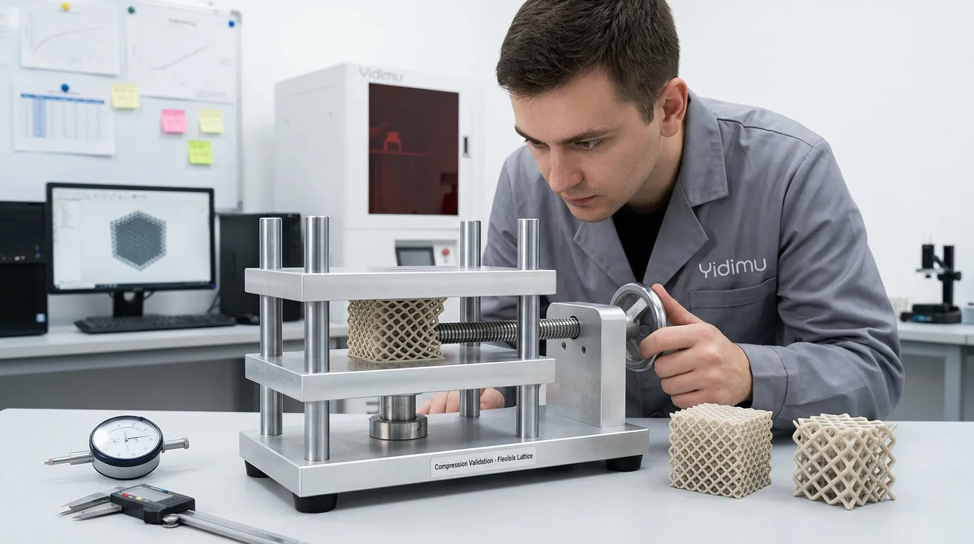
A controlled compression or fit check can reveal differences between lattice variants that are not obvious in CAD. The goal is to compare representative parts under a defined project condition—not to claim a universal rebound value, fatigue life or certified performance.
FROM FLEXIBLE CAD TO EVALUATED PART
A flexible sample is not ready for meaningful comparison immediately after printing. Cleaning access, complete drying, UV post-curing and finishing affect the condition in which the part is evaluated.
EQUIPMENT & MATERIAL MATCHING
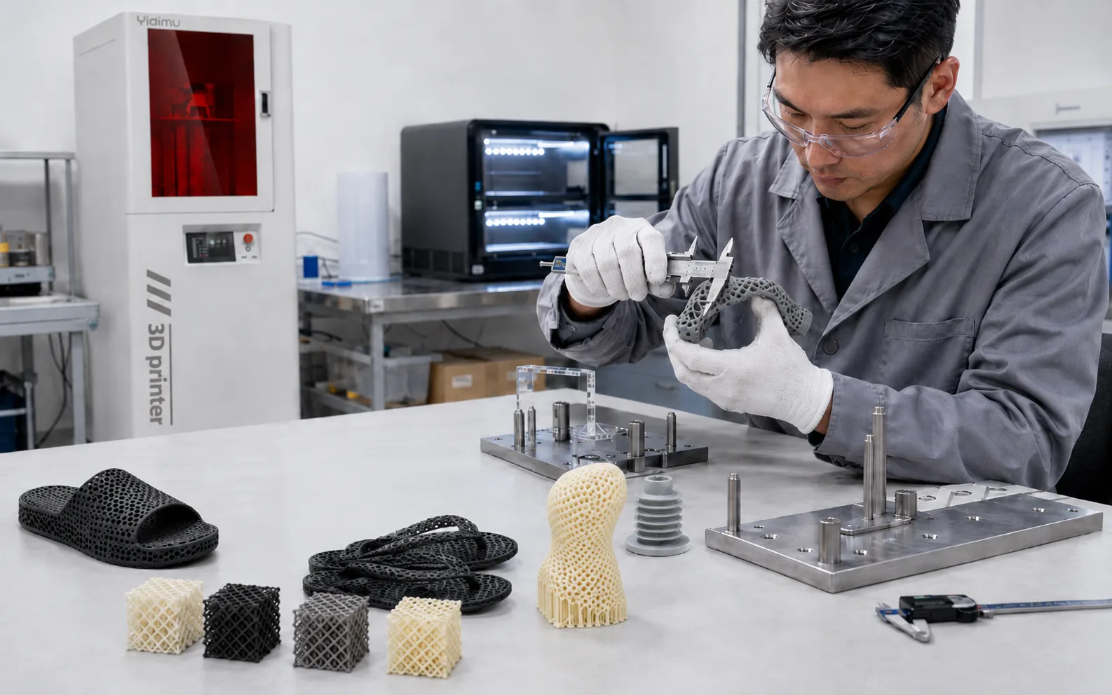
Build size, lattice detail, part orientation, material compatibility, post-processing access and expected output should be reviewed together. The application page below summarizes two current YIDIMU flexible-system paths without replacing the product documentation.
Flex G2 is positioned for complex lattices, cushioning structures and flexible components. Current YIDIMU product information lists a 14-inch 16K system, a 302 × 162 × 370 mm build volume and a 50A–90A elastomer material-hardness range.
Flex Pro is positioned as a floor-standing large-format light-curing system for flexible elastomer parts. Current YIDIMU information lists a 450 × 253 mm build area, a customizable 400–600 mm build height and support for 50A–90A flexible materials.
Use current YIDIMU resin documentation and printer compatibility information to select a flexible or elastomer photopolymer resin. Do not infer end-part performance from a hardness label alone.
Plan washing, complete drying and UV post-curing around the actual lattice size, drainage access and batch volume. Supporting equipment should be sized to the real workflow.
WHAT SHOULD BE VALIDATED?
A useful flexible-part review connects what can be seen and measured on the finished sample to the real project requirement.
Cell shape, thin features, wall transitions, internal openings and areas where local deformation is expected.
Visible texture, support-contact zones, finishing needs and the surfaces that matter to the intended product review.
Direction of bending or deformation under the defined evaluation setup rather than an undefined “softness” description.
How the representative geometry compresses under the project-specific fixture, force or displacement method you actually use.
Record this only when it is actually measured using a defined method, timing and post-cure condition.
Interfaces with mating parts, footwear components, housings, straps or other relevant assembly surfaces.
Identify the dimensions that affect fit, clearance, local wall thickness, attachment features or assembly.
Confirm that compared samples have completed the required washing, complete drying and UV post-curing workflow.
Check how the flexible part locates, compresses, moves or contacts neighboring components in the intended prototype assembly.
SAMPLE VALIDATION
A representative model gives the application team a practical basis for reviewing printability, resin matching, support strategy, cleaning access and the finished evaluation condition.
Include the information that changes the decision:
The request page is the current project-contact route. This application page does not create a separate or simulated upload tool.
Use a real lattice, sole, cushioning structure or elastomer engineering part to compare the complete flexible resin 3D printing workflow. For broader process guidance, review the YIDIMU technical resources before finalizing equipment and material choices.