
Eternal M1
Consider M1 when the part geometry and planned build layout fit its available build envelope and workflow.
View Eternal M1 →Engineering Application Solution
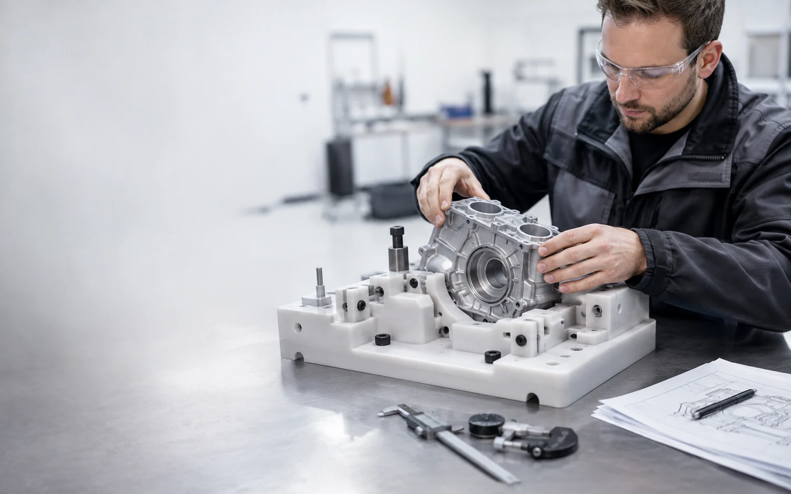
Use resin 3D printing to turn digital designs into physical jigs, positioning tools, checking fixtures and engineering prototypes for fit, assembly and application validation.
Start With the Task
A useful 3D printed jig or engineering prototype starts with the real manufacturing question: what must the part locate, hold, align, clear, mate with, or allow an operator to inspect? The printing process should then be planned around those interfaces and the condition in which the finished part will actually be checked.
Typical Parts
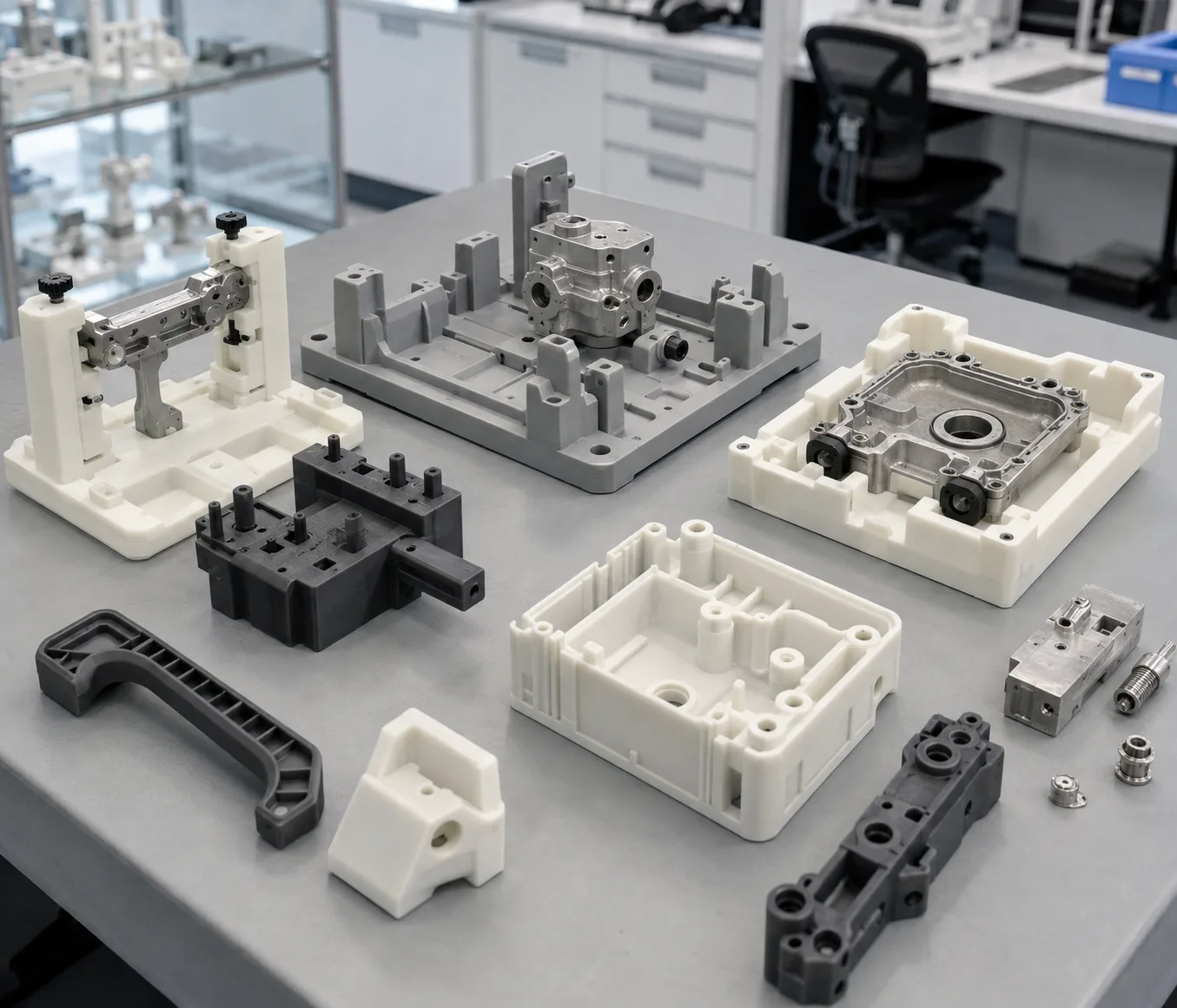
Resin 3D printing can be useful when a team needs a physical part quickly for positioning, checking, assembly review, design iteration or process planning. The value comes from matching the printed geometry to a defined engineering task.
A printed resin fixture should not be assumed to replace a metal fixture or to be suitable for continuous production use. Suitability must be evaluated against load, temperature, chemical exposure, dimensional requirements, material behavior and the expected use cycle.
Design Around the Real Task
The first design decision is not “how accurate can the printer be?” It is how the fixture will reference the real part, where the operator needs access, which surfaces are critical and which printed regions can tolerate support contact or finishing.
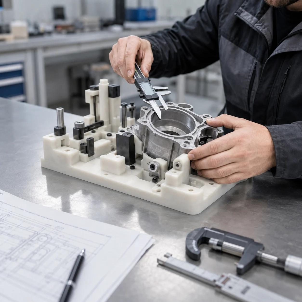
From CAD to Evaluated Fixture
A part that has just left the printer is not the final validation state. Geometry review, orientation, support strategy, washing, complete drying, UV post-curing, finishing and inspection can all influence the part that ultimately reaches the engineering bench.
Define geometry, dimensions, interfaces and the intended task.
Check wall sections, holes, clearances, access and measurable features.
Protect critical surfaces and plan support contact and drainage.
Print the representative geometry using a compatible process.
Remove uncured surface resin using the material-appropriate method.
Confirm recesses, holes and cavities are free of residual wash liquid.
Follow the validated material workflow before final evaluation.
Use the sequence appropriate to the material, geometry and surface need.
Measure critical features and check mating relationships.
Evaluate the fixture or prototype under its actual intended conditions.
The exact sequence for support removal and UV post-curing can vary with resin, geometry and the validated process. Follow the applicable material and equipment instructions rather than assuming one universal sequence.
Printer & Material Selection
Printer selection depends on the part envelope, geometry, build layout and required workflow. Material selection depends on stiffness, surface requirements, dimensional behavior, operating environment and what the prototype is expected to prove.
A representative sample is more useful than choosing from a single headline specification when critical interfaces or application conditions matter.
Consider M1 when the part geometry and planned build layout fit its available build envelope and workflow.
View Eternal M1 →Consider M2 when the project requires a larger build envelope for the part or multi-part layout.
View Eternal M2 →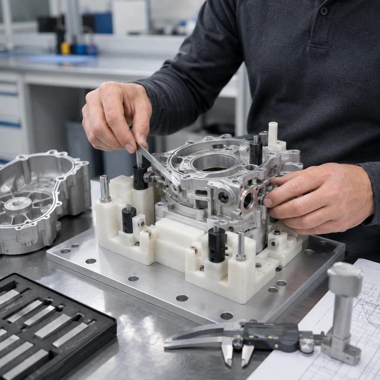
Validate Before Deployment
Fixture suitability cannot be established by appearance alone. Print a representative part, complete the required post-processing, and evaluate the dimensions and interfaces that matter to the application.
Exact tolerance, load capacity, temperature resistance, service life and cycle life should be established from the selected material, complete process and project-specific testing—not assumed from the application category.
Related Technical Resources
Start With Your Part
Share your model, dimensions, intended use, material requirements, critical interfaces and quantity. The project can then be reviewed around the actual geometry, printing workflow, post-processing and validation needs.