
Process & Application Validation
Resin Prototype to Injection Molded Part Workflow
How to use resin 3D printed parts to answer design questions before a tool is cut — and where the printed part stops being valid evidence for a molded part.
- What each prototype stage is actually able to answer
- Which mold-specific checks belong in CAD review, not on the printed part
- What the moulder needs in the handoff package
- How to compare first-shot samples against the drawing
- Where photopolymer behaviour and thermoplastic behaviour diverge
Direct Answer
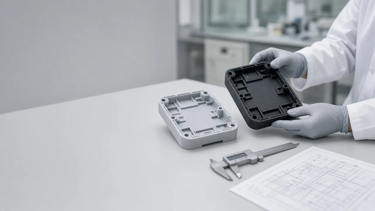
A resin prototype to injection molded part workflow moves a design through physical checks before steel is cut. Printed parts are used to review form, fit and assembly, and to surface design questions that are inexpensive to fix in CAD and expensive to fix in a mold. The workflow then adds a design-for-manufacturing review covering draft, wall sections, ribs, bosses, parting line and ejection, a documented handoff to the moulder, and a measured comparison of first-shot samples against the drawing. The printed part is evidence for a geometry decision. It is not a preview of molded material behaviour, and treating those two roles as interchangeable is where most late tooling changes originate.
Key Takeaways
- Define what each printed part must prove before printing it; an undefined prototype produces an undefined review.
- Draft, uniform wall thickness, gate location, weld lines and ejection are mold constraints. A printed part cannot confirm or refute them.
- Photopolymer resin and molded thermoplastic are different material classes. Stiffness, impact behaviour, creep, chemical resistance and long-term stability do not transfer.
- Printer specifications such as display resolution and XY pixel size describe the equipment, not the finished part.
- Dimensional comparison is only meaningful when the printed part has been washed, fully dried and UV post-cured, and when both parts are measured the same way.
- Shrinkage and tool compensation come from the moulder and the polymer supplier's data, not from a printed sample.
Two Different Forming Processes, Two Different Kinds of Evidence
Resin printing builds a part layer by layer from a photopolymer that is cured by UV exposure. Injection molding forces a molten thermoplastic into a closed steel cavity, where it packs, cools and is ejected. The geometry that survives well in one process is not automatically the geometry that survives well in the other.
A note on terminology: YIDIMU Eternal M1 and Eternal M2 use LCD masked exposure — masked stereolithography — rather than laser-scanned SLA. Both are often described as "SLA" in general industry usage, but the exposure method is a mask, not a scanning laser beam.
| Aspect | Resin 3D printing (LCD masked exposure) | Injection molding |
|---|---|---|
| Material class | UV-cured photopolymer, thermoset behaviour | Thermoplastic, grade-specific behaviour per the polymer datasheet |
| Geometry freedom | Undercuts and internal features are limited mainly by drainage, supports and cleaning access | Limited by parting line, draft, ejection and side actions |
| Wall thickness | Uneven walls are printable within process limits | Uneven walls drive sink, warpage and packing problems |
| Directional behaviour | Layer-wise build; properties can differ with build direction | Flow-related orientation, weld lines and gate effects |
| Change cost | Design revision and reprint | Tool modification, often irreversible |
| Primary validation role | Form, fit, assembly, ergonomics, review of geometry | Production material, surface, cycle and repeat output |
Terminology That Has to Stay Separate
Most disputes between a design team and a moulder are terminology problems before they are engineering problems. The words below are not synonyms, and a specification sheet uses several of them in ways that a finished part never guarantees.
| Term | What it describes | Common misuse |
|---|---|---|
| Resolution | The smallest addressable step of an imaging or motion system | Quoted as if it were finished-part accuracy |
| XY pixel size | Display sampling pitch in the build plane | Converted into a claimed dimensional tolerance |
| Layer height | Vertical increment per exposure | Confused with achievable Z accuracy |
| Accuracy | Closeness of a measured value to the nominal value | Assumed from equipment specification alone |
| Precision | Spread of repeated measurements, regardless of nominal | Used interchangeably with accuracy |
| Repeatability | Agreement between runs under the same conditions, same setup, same operator | Extended to different machines or sites |
| Reproducibility | Agreement across different operators, machines or locations | Assumed once one machine repeats well |
| Tolerance | The permitted range defined on the drawing | Treated as a property the process supplies by default |
| Deviation | Measured difference between actual and nominal | Reported without stating the measurement method |
Resolution is not accuracy. A finer display grid or a thinner layer changes how geometry is sampled; it does not by itself determine what a caliper or CMM reads on a finished part. Results are affected by machine condition, resin and batch, temperature, geometry, orientation, supports, exposure, layer height, platform condition, washing, complete drying, UV post-curing and the measurement method.
Stage 1 — Define What Each Printed Part Must Prove
Before a file is sliced, write down the question the part has to answer. A part printed without a stated review question tends to be judged on surface appearance, which is rarely the decision that matters at that point in the programme.
Concept and appearance review
Proportion, radii, transitions, grip surfaces and overall visual balance. Surface finish expectations should be set explicitly, since post-processing and finishing determine what the reviewer sees. Guidance on planning visible surfaces is covered in resin 3D printing for appearance prototypes.
Fit and assembly review
Mating features, hole positions, clearances, connector interfaces and assembly sequence against real hardware. This is where printed parts contribute most, because interference is visible immediately and correcting it in CAD costs nothing compared with a tool change.
Limited functional review
Movement, access, cable routing, latch travel and similar geometry-led interactions can be observed where the resin and test conditions are appropriate. Load capacity, impact behaviour, fatigue life and environmental durability of the eventual molded part are not established by a printed sample. The appearance, fit and functional validation page sets out how these categories differ.
Stage 2 — Run the DFM Review on the CAD Model
Design-for-manufacturing review for injection molding happens in CAD and in discussion with the moulder. The printed part is a useful reference object during that discussion, but it cannot validate any of the following.
- Draft. Faces parallel to the draw direction need draft to release. Required angles depend on depth, texture and polymer, and come from the moulder.
- Wall thickness. Nominal wall should be as uniform as the function allows. Thick sections invite sink and voids; abrupt transitions invite warpage.
- Ribs and bosses. Rib thickness relative to the adjoining wall, rib height, and boss wall and gusset design all follow molding rules that have no printed equivalent.
- Parting line and undercuts. Every undercut is a decision about lifters, side actions, tool cost and cycle time.
- Gate and flow. Gate type and position influence weld line location, cosmetic surfaces, fill balance and residual stress.
- Ejection. Ejector pin positions leave marks and need adequate support area; they may conflict with cosmetic or sealing surfaces.
- Shrinkage. Mold shrinkage is polymer- and grade-specific and is taken from the material supplier's data and the moulder's experience with that grade. A printed part gives no information about it.
Any published shrinkage range, draft recommendation or wall-thickness rule you use in this review comes from the polymer supplier, the moulder or an industry reference. Such figures are not YIDIMU performance statements and do not describe printed-part behaviour.
Stage 3 — Build the Handoff Package
The transition point where information is most often lost is the handoff to the tool shop. A complete package reduces the number of assumptions the moulder has to make.
- Native CAD plus a neutral format (STEP), with the revision clearly identified.
- A drawing that separates critical dimensions from reference dimensions, with tolerances assigned only where function requires them.
- Nominated polymer and grade, or the property requirements if the grade is still open.
- Cosmetic surface definition: which faces are visible, required texture, and acceptable gate and ejector locations.
- Annual and initial volumes, since these drive tool class and cavitation.
- The printed prototypes themselves, clearly labelled as geometry references rather than material samples.
Labelling matters more than it sounds. A moulder handed an unlabelled resin part may reasonably read its stiffness or surface as a target, which sets an expectation nobody intended to set.
Stage 4 — Review First-Shot Samples
When T1 samples arrive, the comparison is between the molded part and the drawing — not between the molded part and the prototype. The prototype's role at this point is to explain intent where a drawing is ambiguous.
Measure the same features, with the same method, datum scheme and fixturing, that were used earlier in the programme. Molded parts continue to change dimensionally after ejection as they cool and relax, so define when measurement takes place relative to molding. Record the observed deviation per feature rather than an overall verdict, since tool correction is done feature by feature.
Working Templates
| Stage | Review question | Resin / process | Features inspected | Acceptance criterion | Decision taken |
|---|---|---|---|---|---|
| Feature | Issue raised | Raised by | Proposed change | CAD revision | Status |
|---|---|---|---|---|---|
| Feature | Nominal | Tolerance | Measurement method | Prototype reading | T1 reading | Deviation | Action |
|---|---|---|---|---|---|---|---|
Reading the Results
Interpretation depends on which stage produced the number. A deviation on a printed prototype tells you about the print process, the post-processing route and the measurement method. A deviation on a T1 sample tells you about the tool, the polymer, the process window and the same measurement method. Neither one validates the other.
When a printed part and a molded part disagree, the useful questions are whether both were measured on the same datums, whether the printed part was fully processed before measuring, whether the molded part had stabilised, and whether the drawing actually specified that feature. Consistent disagreement in one direction across several features usually points at a datum or fixturing difference rather than at either process.
An acceptable prototype does not indicate an acceptable tool, and an acceptable T1 does not by itself indicate a stable production process. Stability is assessed across repeated runs on the same setup, with reproducibility considered separately if a second cavity, machine or site is involved.
Common Mistakes
- Sending an unlabelled prototype to the tool shop. Without a stated purpose, the recipient assigns one.
- Judging molded material behaviour from a printed part. Snap-fit deflection, living hinges, impact resistance and chemical exposure require the production polymer.
- Applying one blanket tolerance to every dimension. This raises tool cost, inflates inspection workload and hides the dimensions that genuinely matter.
- Deferring the DFM review until after prototypes look right. A geometry approved without draft or ejection review often has to be reopened.
- Measuring before the process is finished. A printed part that has not been washed, fully dried and UV post-cured is not in a comparable condition.
- Reading printer specifications as part tolerances. Display resolution, XY pixel size and layer height describe the equipment.
- Changing several variables between prototype rounds. Resin, orientation and geometry changed together make the result uninterpretable.
Limits and Validation
This workflow reduces avoidable rework; it does not remove risk from tooling. Printed prototypes cannot establish molded mechanical properties, weld line strength, long-term dimensional stability, regulatory conformity or cycle time. Where the design depends on those properties, validation requires the production polymer — through machined blanks, a soft or bridge tool, or the production tool itself.
Where a printed prototype's own dimensional behaviour matters to a decision, it should be established empirically for the actual geometry, resin and processing route rather than derived from published equipment figures. Print several units under the same conditions, process them identically, and measure them with a defined method before drawing any conclusion about consistency. Material handling, curing and safety follow the TDS, SDS and IFU for the resin in use.
If printed parts are also intended to serve as short-run production or bridge parts, the evaluation changes and is covered separately in resin 3D printing for low-volume manufacturing.
Relevant YIDIMU Systems
Eternal M2
Eternal M2 is an industrial LCD vat photopolymerization system. Published product data lists a 353 × 198 × 400 mm build volume, a 16-inch 7680 × 4320 display, approximately 46 μm XY pixel size, a 0.02–0.10 mm layer thickness range and a 405 nm UV wavelength, with STL and OBJ file support prepared in ChiTuBox or ChiTuBox Pro. The listed build envelope is relevant to pre-tooling work when a housing or cover would otherwise be split, or when several parts of an assembly are printed in one layout for a fit review.
The XY pixel size figure describes display sampling in the build plane and is not a finished-part accuracy statement. Larger-part considerations such as orientation, support load, drainage and post-processing access are discussed in the guide to large-format resin 3D printing for industrial parts. Resin selection should be confirmed against current material documentation on the photopolymer resin pages rather than assumed from wavelength compatibility.
Checklist
- Review question written down for each prototype round
- Critical dimensions separated from reference dimensions on the drawing
- Polymer and grade nominated, or property requirements stated
- DFM review completed on CAD: draft, wall, ribs, bosses, parting line, gate, ejection
- Undercuts identified and their tooling implications accepted
- Cosmetic surfaces, texture and acceptable mark locations defined
- Prototypes washed, fully dried and UV post-cured before inspection
- Measurement method, datums and fixturing documented and reused
- Prototypes labelled as geometry references when handed over
- T1 measurement timing defined relative to molding
- Deviations recorded per feature, with an action assigned to each
FAQ
Can a resin prototype replace a T1 sample?
No. A printed prototype validates geometry and assembly intent. A T1 sample validates the tool, the polymer and the process window. They answer different questions and both stages are normally required.
Should the prototype be printed at the shrink-compensated size?
Generally no. Shrink compensation is applied to the cavity by the moulder for the nominated polymer. Printing a prototype at the compensated size introduces an offset that has to be corrected in every subsequent review.
How many prototype rounds are appropriate?
As many as the open review questions require, with one round per group of related questions. Changing many variables at once between rounds makes the comparison difficult to interpret, which is a more common problem than printing too few parts.
Can printed parts be used to check snap-fits?
They can show whether the geometry engages and where interference occurs. They do not establish retention force, deflection at failure or repeated-cycle behaviour in the production polymer, which requires testing in that material.
Does a finer XY pixel size produce a prototype closer to the molded part?
Not directly. Sampling in the build plane affects how fine geometry is reproduced, while agreement between a prototype and a molded part depends on the design, both processes, the post-processing route and the measurement method used on each.
Which parts of the assembly are worth printing?
Those carrying unresolved interfaces, unusual geometry, cosmetic risk or assembly-sequence uncertainty. Parts that are simple, already proven or carried over from a previous programme rarely justify a printed round.
Discuss Your Project
To review a specific part against this workflow, share the CAD or STL file, overall dimensions, application, critical features and their tolerances, the intended production polymer, quantities, surface requirements and the inspection method you plan to use.
With that information, printer envelope, resin category and post-processing route can be discussed against the actual part rather than against a specification table.
Submit your model and project requirements or contact YIDIMU.