
Layer Height vs Resolution in Resin 3D Printing
Layer height and resolution describe different axes. In a resin 3D printer, layer height is the Z step between exposed slices. It controls stair-stepping on sloped and curved surfaces and how many layers a build needs. Resolution usually means the XY side: the LCD's pixel count and the pixel size it produces at the build plane, which sets in-plane edge detail. Neither number is dimensional accuracy. That comes from exposure, resin behavior, orientation, supports and post-curing, and it has to be measured on real parts.
This guide is written for LCD masked-exposure (MSLA) resin printing, the architecture used in YIDIMU's Eternal series. The Z-axis logic applies to laser SLA and DLP as well. The XY discussion doesn't transfer directly, because a scanned laser spot or projection optics, not an LCD mask, define the edge in those systems. FDM is different again: nozzle size and bead width dominate what you see.
What layer height controls in resin printing
Layer height sets how far the build platform moves between exposures, so it fixes how finely the model is sampled in Z. The slicer cuts the CAD model into slices of that thickness, and each slice becomes one mask image. The printer cures the image, separates the part from the film, moves up one layer and repeats.
For layers to bond, light has to cure slightly deeper than one layer thickness, so every exposure reaches into the layer below. The standard way to describe this is the Jacobs working curve: cure depth increases with the logarithm of exposure, scaled by how far light penetrates the resin. A resin profile is tuned so cure depth comfortably exceeds the chosen layer height. That's why changing layer height without touching exposure rarely works. A thicker layer at the old exposure can delaminate, and a thinner one ends up overcured.
Those working-curve values aren't universal constants. In a published interlaboratory study, 24 labs measured aliquots of one resin batch and reported penetration depths that differed by up to about 7x and critical exposures that differed by up to about 70x, with procedure, light engines and thickness measurement all contributing. An exposure copied from another printer is a starting guess, not a setting.
Layer height also drives build time. An MSLA printer exposes a whole layer at once, so time scales mainly with layer count. Halve the layer height and you roughly double the exposures and the separations. That second part gets overlooked. On a large cross-section, a thinner layer doesn't make each separation much gentler, so the same supports now carry twice as many load cycles before the part is finished.
What "resolution" means on a resin printer spec sheet
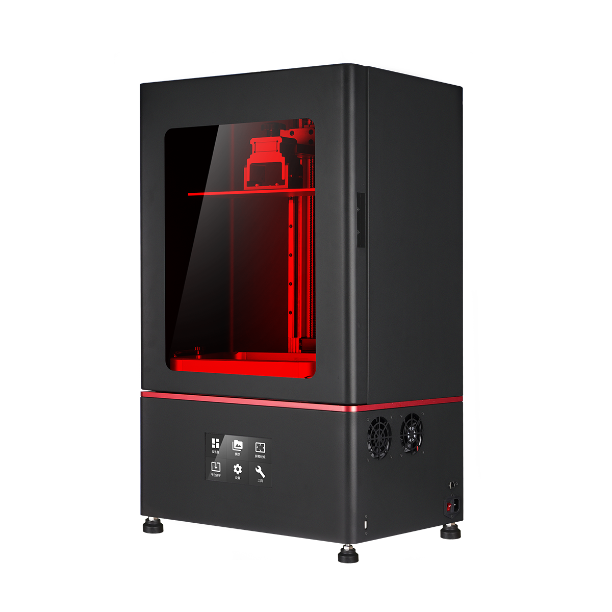
On LCD resin printers, "resolution" almost always refers to XY. The headline figure, such as 8K or 7680 × 4320, is the pixel count of the masking screen. What actually shapes edges is the physical pixel size at the build plane: printable width divided by pixel count, checked separately for X and Y. Two printers with the same K label can have different pixel sizes if their screens differ in size, which is covered in more detail in our comparison of 8K, 12K and 16K resin printers.
Some datasheets and slicers also call layer height "Z resolution." That's legitimate usage, but it's the reason any resolution figure in a quote deserves one follow-up question: which axis?
A pixel is a sampling interval, not the size of a cured edge. Light spreads slightly and resin responds to a dose threshold, so the cured boundary is never a perfect grid of squares. Anti-aliasing, which partially exposes edge pixels, smooths visible stepping but also moves where the edge cures. On a bore or a boss, that can show up as a small dimensional shift. The relationship between pixel pitch and finished tolerance is covered in pixel size vs print accuracy.
| Question | Layer height | XY resolution (pixel size) |
|---|---|---|
| Axis | Z, the build direction | X and Y, the build plane |
| Who sets it | Chosen in the slicer, within the machine's range and the resin profile | Fixed by the screen and optical path; anti-aliasing changes edge rendering, not pixel size |
| Where you see it | Steps on sloped and curved surfaces, contour rings on shallow domes | Stepping along curved or angled edges in the build plane, limits on fine in-plane features |
| Cost of going finer | More layers, longer builds, more separation cycles | Nothing per job; at purchase it trades against build area for a given screen size |
| What it doesn't tell you | Z accuracy, layer bonding, or finish on vertical walls | Dimensional tolerance or the smallest feature that prints reliably |
Where layer lines actually show up on a part
Stair-stepping depends on surface angle as much as on layer height. Slicing research describes it with cusp height, the deviation between the stepped surface and the intended one. Cusp height drops to zero on vertical walls and is largest on surfaces that are close to horizontal without being flat.
The geometry is easy to check. On a 45° surface, each step is as wide as the layer is thick. At 10° from horizontal, each step is about 5.7 times the layer height wide. With 50 µm layers, used here only as a worked example, that's a terrace close to 0.3 mm across, wide enough to catch light.
That's why the tops of domes, shallow draft faces and gently curved housings show concentric rings that look like contour lines on a map, while the steep sides of the same part look smooth. Tilting the part so those shallow faces sit steeper often removes more visible stepping than halving the layer height, and it doesn't double the build time. It does move supports, and with them the support marks, so it's a trade rather than a free fix.
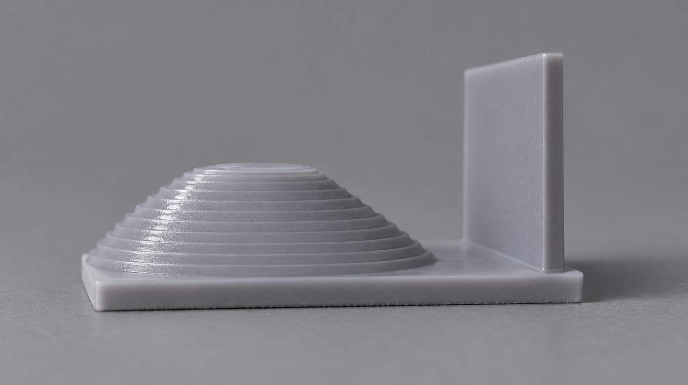
Regular lines on a truly vertical wall are a different problem. They aren't geometric steps, because a vertical wall has none. They usually mean something changed from layer to layer: Z motion, exposure consistency, resin temperature, or the part shifting slightly during separation. Thinner layers won't fix them.
Why thinner layers don't guarantee better Z accuracy
Layer height is the nominal Z increment. Z accuracy is how close the finished part's heights come to the drawing. The two are separate, and the largest Z errors usually come from somewhere else.
Overcure on downward-facing surfaces. Because each exposure cures deeper than one layer, the first layer of any overhang grows down into space that should stay empty. Horizontal holes show it clearly: the top of the bore faces down, so the hole often comes out slightly short in Z and a little oval. How much depends on exposure and the resin's penetration depth, not on layer height alone.
Bottom layers. The first layers get heavy exposure so they stick to the platform, and they tend to flare outward. Parts printed directly on the plate often carry that error at their base, which is one reason industrial parts usually sit on supports.
Z mechanics and separation. Platform alignment, lead screw behavior and the elastic stretch of supports during separation all affect where each layer actually forms.
Cure shrinkage and post-processing. Photopolymers shrink as they cure, and dimensions can keep moving through washing, drying and post-curing. Measure in the final state, using a routine like the one in our resin print quality inspection checklist.
If a Z dimension is out, check orientation, overcure and post-cure condition before reaching for a thinner layer.
How layer height and XY pixel size work together
Neither axis compensates for the other, so matching both to the geometry matters more than pushing either one to its limit. Orientation decides which axis draws which feature.
Stand a cylinder upright and its circumference is drawn by pixels in the build plane, while its length is drawn by layers. Lay the same cylinder on its side and the roles swap: now the round profile is built from stacked layers and shows stair-steps near its top and bottom, while the length is set by pixels. When one feature carries the requirement, such as a sealing edge, a fine emboss or a curved cosmetic face, orient the part so that feature is drawn by the axis that samples it best, then check what that orientation does to supports and overhangs.
How to choose a layer height for a production part
Start from the resin's validated profile, and change layer height only for a reason you can name. The table below is a way to frame that decision, not a set of fixed values.
| Part situation | Layer height direction | What to check before committing |
|---|---|---|
| Large housings, fixtures and models with mostly steep walls | Thicker, within the resin's validated range; spend effort on orientation instead | Shallow faces, support marks, build time |
| Shallow domes, fine embossing, organic surfaces | Reorient first; thinner layers if rings still show | Surface under raking light after post-cure and finishing |
| Dental models and parts with fits along Z | Keep the validated material profile; revalidate before any change | Measured heights, bore shape, seating of mating parts |
| Tall parts with many layers | Thicker layers reduce separation cycles | Support stiffness, layer shift, cycle time |
| Flexible and elastomer parts | Follow the elastomer's own profile; flexible resins behave differently during separation | Geometry measured in a defined, unloaded state |
How to test layer height on your own part
A spec sheet can't tell you which layer height a specific part needs. A two-build comparison can.
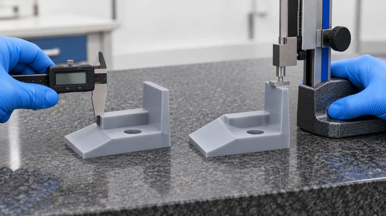
Pick a representative file that includes a shallow slope, a vertical wall, a horizontal hole and a Z step you can measure. The real part is better than a generic coupon.
Print it at two layer heights, each with its matching exposure profile, in the same orientation and the same platform position.
Wash, dry completely and post-cure both exactly as production would.
Measure the Z step, the hole in both directions and the overall height, and inspect the shallow surface under raking light.
Record build time and any failed, shifted or distorted parts.
If the thicker layer meets the drawing and the surface requirement, it's usually the better production setting. The result holds for that resin, orientation and machine. Change any of them and repeat the check.
Layer height and pixel size on YIDIMU systems
The values below are the nominal ranges published in YIDIMU product documentation. They describe what each machine can be set to and how its screen samples the build plane. They are not finished-part tolerances.
| System | Exposure method | XY pixel size | Layer thickness range |
|---|---|---|---|
| Eternal D1 | LCD masked exposure | X 16.8 µm / Y 24.8 µm | 0.02–0.1 mm |
| Eternal Y8 | LCD masked exposure | 29.7 µm | 0.025–0.1 mm |
| Eternal M1 | LCD masked exposure | 46 µm | 0.02–0.1 mm |
| Eternal M2 | LCD masked exposure | 46 µm | 0.02–0.1 mm |
D1 and M2 share a layer thickness range but differ in pixel size by more than a factor of two in X. That's the practical reminder: layer height and XY resolution are independent specifications, and each machine should be judged on the parts it has to make.
Next step: test the part, not the spec
If you're choosing between layer settings or printers, send a representative CAD file with the critical dimensions and surfaces marked. Submit your model and YIDIMU's application team can print it on a relevant system, post-process it the way production would, and show where layer height and pixel size matter for that part.
References
Results of an interlaboratory study on the working curve in vat photopolymerization (PubMed Central)
Results of an interlaboratory study on the working curve in vat photopolymerization II: Towards a standardized method (Additive Manufacturing)
Dolenc, A. and Mäkelä, I. Slicing procedures for layered manufacturing techniques (Computer-Aided Design, 26(2), 119–126)
Author: [Name], [Title], [one line of relevant resin-printing experience]
Technical reviewer: [Name], [Title]
Last updated: [Date]