Application Engineering

Industrial Models & Engineering Validation

Turn engineering CAD into physical resin models for dimensional review, interface checks, assembly evaluation and application-specific validation.

Define the engineering requirement first. Then select the printer, resin and process around what the part must prove.

The engineering question

Can the printed model reproduce the geometry and interfaces needed for a meaningful engineering decision?

Print Complete Post-Processing Measure Assemble Inspect Compare to Requirement

What Are You Validating?

Focus on the geometry that controls the decision.

Industrial model 3D printing is useful when a physical part must be checked against a drawing, CAD model, mating component or agreed validation plan—not simply viewed as a demonstration print.

01

Dimensional Geometry

Review the dimensions and feature relationships that matter to the engineering decision. The acceptance method should be defined before printing.

  • Overall envelope
  • Hole locations
  • Wall geometry
  • Slots and bosses
  • Datum-related features
  • Edge relationships
02

Interfaces & Fit

Check how the resin engineering model locates, mounts or clears adjacent components under the intended assembly condition.

  • Mating surfaces
  • Locating features
  • Mounting points
  • Connectors
  • Assembly interfaces
  • Component clearance
03

Structural Geometry

Use the model to review ribs, walls, transitions, reinforcement shapes and other structural geometry. This does not by itself validate final strength, impact life, fatigue life or load rating.

  • Ribs and walls
  • Internal geometry
  • Section transitions
  • Reinforcement forms
04

Engineering Housings & Components

Evaluate representative industrial geometry such as housings, covers, brackets, control-panel parts, machine components and other application-specific models.

  • Housings
  • Covers
  • Brackets
  • Equipment shells
  • Machine components
05

Large Industrial Models

A larger model may reduce unnecessary splitting, but one-piece printing should only be selected after checking orientation, support space, drainage, removal, washing, complete drying, UV post-curing and final inspection.

  • Large housings
  • Prototype shells
  • One-piece models where practical
  • Fewer avoidable joints
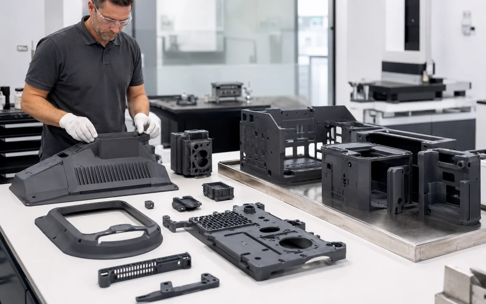
Fully post-processed resin engineering housings, brackets and industrial models ready for inspection

Representative Industrial Geometry

Evaluate finished models—not green-state prints.

Parts intended for dimensional or interface decisions should follow the specified washing, complete drying, UV post-curing and finishing workflow before final inspection.

Start With the Engineering Requirement

Engineering validation begins with what the part must prove.

A printer specification is not an acceptance criterion. Define the requirement first, then build the printing and inspection workflow around it.

  • Source definitionConfirm the CAD revision, drawing, units and intended part state before preparing the build.
  • Critical dimensionsIdentify dimensions, datums, holes, interfaces and feature relationships that control the engineering decision.
  • Mating relationshipsDefine the components, fasteners, locating features, clearances or assembly references used for the check.
  • Inspection methodDecide how the critical features will be measured or compared after the required post-processing is complete.
  • Surface prioritiesMark appearance surfaces, support-sensitive zones and areas that must remain accessible for inspection.
  • Material directionState whether the model is primarily for geometry, short-term function or another requirement that affects resin selection.
  • Operating conditionsRecord any temperature, chemical, load or service conditions that require separate material-performance validation.

From CAD to Evaluated Industrial Model

Treat printing, post-processing and inspection as one controlled workflow.

A part leaving the printer is not automatically in its final inspection state. The sequence must match the resin, geometry and validation plan.

  1. Engineering CAD
  2. Define Critical Features
  3. Model Review
  4. Printer & Resin Selection
  5. Orientation & Supports
  6. Resin 3D Printing
  7. Washing
  8. Complete Drying
  9. UV Post-Curing
  10. Support Removal / Finishing
  11. Dimensional Inspection
  12. Assembly / Interface Review
  13. Engineering Decision

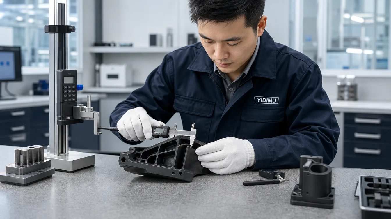
Inspection rule: final dimensional acceptance should be based on the part after the required cleaning, complete drying, UV post-curing and finishing sequence—not on a wet or partially cured print just removed from the machine.

Engineer checking a finished resin model with dimensional inspection tools on a precision workbench

Measure What Controls the Decision

Do not convert a screen specification into a finished-part tolerance.

Screen resolution, pixel size and layer thickness describe parts of the printing system. They do not independently define the tolerance of a fully post-processed industrial model.

  • Datums
  • Hole-to-hole relationships
  • Mounting interfaces
  • Mating surfaces
  • Slots
  • Wall sections
  • Critical edges
  • Overall envelope
  • Assembly clearance
  • Flatness-sensitive areas where relevant

Acceptance criteria should come from the engineering drawing, CAD, assembly requirement, application requirement or an agreed validation plan. There is no single website-wide tolerance that can replace part-specific inspection.

Define the Technical Boundary

Industrial models are not automatically final parts.

A model can reproduce useful geometry without proving every property required in the final service environment. Keep geometry validation and material-performance validation separate.

Can support

Geometry validation

After the required post-processing, a representative resin model can be used to evaluate defined geometric and assembly relationships.

  • Geometry
  • Fit
  • Interfaces
  • Surface
  • Assembly
  • Selected functional relationships
Requires separate evidence

Final material performance

Correct dimensions and appearance do not prove long-term service performance. The actual resin, process, environment and test method must be evaluated for the intended use.

  • Impact resistance
  • Heat resistance
  • UV resistance
  • Fatigue life
  • Chemical resistance
  • Creep
  • Long-term loading
  • Outdoor durability

Assembly & Interface Review

Use the real mating condition whenever practical.

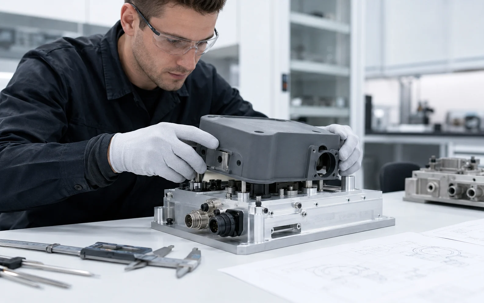
Position the fully post-processed resin component against the actual or representative mechanical components used in the project. Review locating features, mounting points, clearances and interface relationships without treating the exercise as a final load or life test.

Fully post-processed resin engineering component being checked against a real mechanical assembly

Printer & Material Selection

Select around the oriented part and the complete workflow.

A nominal build volume is only the starting point. The usable production space must accommodate orientation, supports, platform-edge clearance, drainage, removal and the downstream washing, complete drying, UV post-curing and inspection process.

  1. 01
    Part envelopeStart from the real model dimensions and the features that must remain inspectable.
  2. 02
    Oriented size & supportsAccount for tilt, support structure, raft or base geometry and clearance from the usable build boundaries.
  3. 03
    Geometry & layoutReview large cross-sections, cavities, drainage, multiple-part layouts and the risk created by a heavily loaded platform.
  4. 04
    Resin requirementMatch the material direction to the intended validation task and confirm printer–resin compatibility through documented settings and testing.
  5. 05
    Post-processing capacityConfirm that washing, drying and curing equipment can handle the same part envelope and production quantity.
  6. 06
    Inspection planPlan how representative critical features will be measured after the final specified process state is reached.

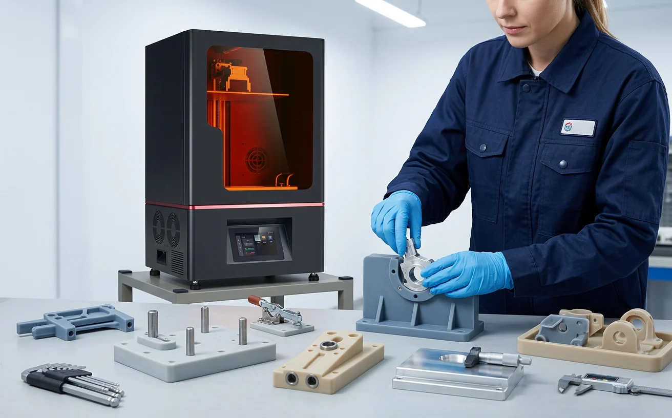
YIDIMU Eternal M1 for industrial resin applications

Evaluate the machine together with the intended resin, oriented build layout, post-processing capacity and representative engineering sample. Final suitability depends on the actual project requirement.

Representative Engineering Validation

Test the part that represents the real requirement.

Before selecting equipment for an industrial workflow, a representative sample can reveal more about the real process than isolated headline specifications.

  1. 01Submit CAD
  2. 02Define Critical Features
  3. 03Print Representative Part
  4. 04Complete Required Post-Processing
  5. 05Measure Critical Dimensions
  6. 06Check Interfaces / Assembly
  7. 07Compare Against Requirements
  8. 08Select Equipment & Workflow

Nominal screen resolution, pixel size, layer thickness or print-speed figures can help describe a system, but they do not replace a representative part that has been processed and inspected under the conditions relevant to your engineering decision.

Start With Your Real Part

Have an Engineering Model to Validate?

Send the model and the requirements that control the engineering decision. YIDIMU can use that information to discuss sample evaluation, equipment, resin and post-processing workflow options.

  • 3D model and CAD revision
  • Overall dimensions
  • Critical dimensions and datums
  • Drawing, where available
  • Material direction
  • Intended use and operating conditions
  • Required quantity
  • Surface requirements
  • Assembly or mating requirements
  • Inspection and acceptance method