
Define the parting line early
Place the split where the mold halves can separate cleanly and where flash can be inspected or trimmed. Avoid making the printed halves depend on long, fragile shutoffs unless they are necessary.
Rapid Tooling · Resin 3D Printing
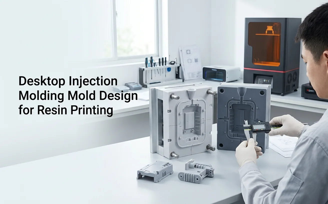
A resin-printed injection mold is not simply a negative copy of the part. The mold must be designed around filling pressure, heat, demolding, parting-line control, venting, local support and the limits of the printed tooling material.
Direct Answer
Desktop injection molding mold design for resin printing should minimize avoidable mechanical and thermal stress while still filling, venting, opening and ejecting reliably. In practice, that means choosing a simple pull direction, adding sufficient draft, keeping the parting surfaces well supported, designing a low-resistance gate, providing an escape path for air, avoiding fragile cavity details, and supporting the printed insert in a rigid mold frame or backing structure when the press setup requires it. The printed mold then has to be fully processed and dimensionally checked before injection trials. Tool life cannot be predicted from CAD alone because it depends on the mold material, injected polymer, melt temperature, pressure, clamp condition, geometry and cycle history.
Undercuts and near-zero draft can turn normal ejection into a destructive load on a polymer tool.
A restrictive gate or long thin flow path can demand more pressure and increase stress on the cavity.
Trapped air can create short shots, burning, incomplete detail or pressure spikes near the end of fill.
The printed insert should not flex excessively under clamping or injection loads.
Parting surfaces, locating features, bores and ejector interfaces may need fitting or secondary machining.
Cycle count is a project outcome, not a universal property of “resin printing.”
Design Logic
A machined metal mold and a photopolymer mold insert do the same basic job—define the cavity, control material flow and release the part—but they do not react to heat and load in the same way. A resin-printed tool can be useful for prototype and low-volume evaluation because the cavity can be changed quickly, but the design has to respect the lower thermal conductivity, different stiffness, possible heat distortion and more limited resistance to repeated mechanical contact.
That changes the engineering priority. Instead of optimizing only the plastic part, you also optimize how much stress the temporary mold sees. Thin standing features, sharp internal corners, unsupported cavity walls, deep textures, aggressive undercuts and high-friction ejection can all shorten the useful life of the printed tool. A geometry that works in steel may need simplification or extra support in a polymer insert.
Place the split where the mold halves can separate cleanly and where flash can be inspected or trimmed. Avoid making the printed halves depend on long, fragile shutoffs unless they are necessary.
Give molded surfaces positive draft and remove unnecessary reverse features. More texture, deeper walls and softer molded polymers may require more release allowance.
A gate that feeds a thick or central region can reduce flow distance. The gate must still be accessible for trimming and should not force the melt through a fragile printed feature.
Provide controlled air escape near flow ends and trapped pockets. Vent dimensions should be matched to the molded polymer and flash tolerance rather than copied blindly from another tool.
Keep enough material behind cavity surfaces and use a rigid holder, frame or backing plate when needed. The goal is to prevent local bending and distribute clamp load.
Use accessible ejector locations or manual release features that push the molded part in a controlled direction. Avoid using screwdrivers or wedges against thin printed edges.
CAD Review
A useful CAD review separates features that affect the molded part from features that protect the printed tool. The mold can then be revised before resin, machine time and injection trials are consumed.
| Design area | Why it matters | What to verify in CAD |
|---|---|---|
| Parting line | Controls mold opening, flash location and alignment. | Continuous shutoff surfaces, practical split direction, access for inspection and finishing. |
| Draft | Reduces friction and ejection force. | Positive draft on walls parallel to pull; extra allowance for depth or texture where needed. |
| Gate | Influences pressure demand, weld lines and fill balance. | Short flow path, enough section for the selected polymer, safe location on the printed tool. |
| Venting | Allows displaced air to leave the cavity. | Vents at end-of-fill regions and isolated pockets without creating unacceptable flash. |
| Cavity support | Limits deflection and cracking under load. | Adequate material behind the cavity and a load path into the mold holder or frame. |
| Locating features | Keeps halves aligned during closing. | Broad, robust alignment geometry; avoid relying on thin resin pins where metal hardware is more appropriate. |
| Ejection | Prevents damage during part removal. | Accessible push points, ejector locations or removable inserts that do not overload thin walls. |
| Finishing allowance | Allows critical dimensions to be corrected after printing. | Stock on faces or bores that may need sanding, drilling, reaming or machining. |
Do not copy a metal mold drawing without review. Features that are routine in hardened steel—thin shutoffs, sharp corners, very small standing pins or high-contact sliding features—can become the first failure points in a photopolymer tool.
Printing & Post-Processing
Choose an orientation that gives the cavity, parting surfaces and locating geometry the most stable result your printer-material combination can provide. If supports touch a critical sealing or cavity surface, their removal can change the local geometry. Large flat blocks may also need an orientation strategy that limits warping. For paired mold halves, keeping the build-direction logic consistent can make dimensional behavior easier to compare during fitting.
The printed mold is usually thicker and more massive than a normal prototype part. Support placement should therefore consider peel or separation loads during printing, drainage, resin trapping and access for cleaning. Hollowing a tool solely to save material can create weak skins or trapped resin if it is not engineered carefully. For an injection insert, stiffness and complete cleaning are more important than minimizing every gram of resin.
Uncured resin left in holes, vents or textured surfaces can affect dimensions and contaminate later steps. After washing, allow the tool to dry completely before UV post-curing. Use the resin supplier’s TDS, SDS, IFU or other formal technical documentation for handling and post-cure conditions. A universal cleaning or curing time should not be assumed across materials.
Inspect the parting surfaces only after the complete print and post-processing sequence. Check flatness, mating contact, locating features, gate entry, vents and any holes for metal pins or ejectors. Critical surfaces can then be fitted by controlled sanding, drilling, reaming or machining if the design includes allowance for it.
Material Boundary
The word “rigid” describes only part of the requirement. A resin-printed mold also experiences heat from the injected polymer, clamp load, cavity pressure, repeated heating and cooling, friction during demolding and local stress around gates, corners and ejector points. A material that prints a good engineering model may still be unsuitable for this environment.
YIDIMU currently publishes industrial model resins, including rigid and ABS-like materials, but the available public product information does not establish those materials as validated injection-mold tooling resins. For that reason, this guide does not assign a mold temperature limit, pressure rating or expected cycle count to any YIDIMU resin. If a project requires resin-printed injection tooling, confirm the candidate resin’s formal technical data and run representative mold trials under the intended thermoplastic and process conditions.
Validation Workflow
The first objective is not a high cycle count. It is to learn whether the mold fills, vents, releases and holds its geometry without damage. Record changes so the next printed revision is based on evidence rather than guesswork.
Check cavity dimensions, flatness, parting contact, gate geometry, vent continuity, inserts and locating features after full post-processing.
Confirm that backing plates, frame, bolts, metal pins or ejector components carry load as intended without point-loading the resin.
Use the molding machine and thermoplastic supplier guidance to establish an appropriate initial process window. Avoid treating one published setup as universal.
Look for short shots, trapped-air marks, flash, gate damage and unusual resistance. Revise flow or venting before increasing stress unnecessarily.
Inspect the molded part and tool after ejection. Scuffing, chipped edges or excessive force can indicate insufficient draft, poor surface condition or a difficult pull direction.
Measure critical areas periodically and log visible wear, distortion or cracks. Stop using a damaged insert before failure creates a safety or quality problem.
Failure Review
| Observed problem | Possible mold-related causes | What to review |
|---|---|---|
| Short shot | Gate too restrictive, long flow path, trapped air, premature cooling. | Gate section and location, venting, part thickness, injected material and process settings. |
| Flash at the split | Parting surface mismatch, insert deflection, insufficient support or excessive process load. | Flatness, mold-holder contact, alignment, clamp condition and filling pressure. |
| Mold cracks near gate | Stress concentration, thin local section or high filling resistance. | Gate transition, local wall thickness, corner radius and support behind the gate. |
| Part sticks in cavity | Insufficient draft, rough surface, deep texture or unfavorable shrink direction. | Pull direction, draft, polish, release strategy and ejector placement. |
| Parting line shifts | Weak alignment features or movement inside the holder. | Locating geometry, frame fit, metal pins and repeatable mold seating. |
| Dimensions drift during trials | Tool heating, creep, wear or progressive damage. | Tool temperature history, support, resin suitability and inspection interval. |
Relevant YIDIMU Systems
The printer is only one part of the rapid-tooling workflow. For a resin-printed injection mold project, the more important question is whether the complete printer, resin, orientation, support, post-processing and inspection process can produce the required mold geometry. YIDIMU’s current industrial range includes Eternal M1 and Eternal M2; both are positioned for industrial resin printing and engineering model work. Final suitability for injection-mold inserts should be confirmed with the intended tooling resin and representative geometry.
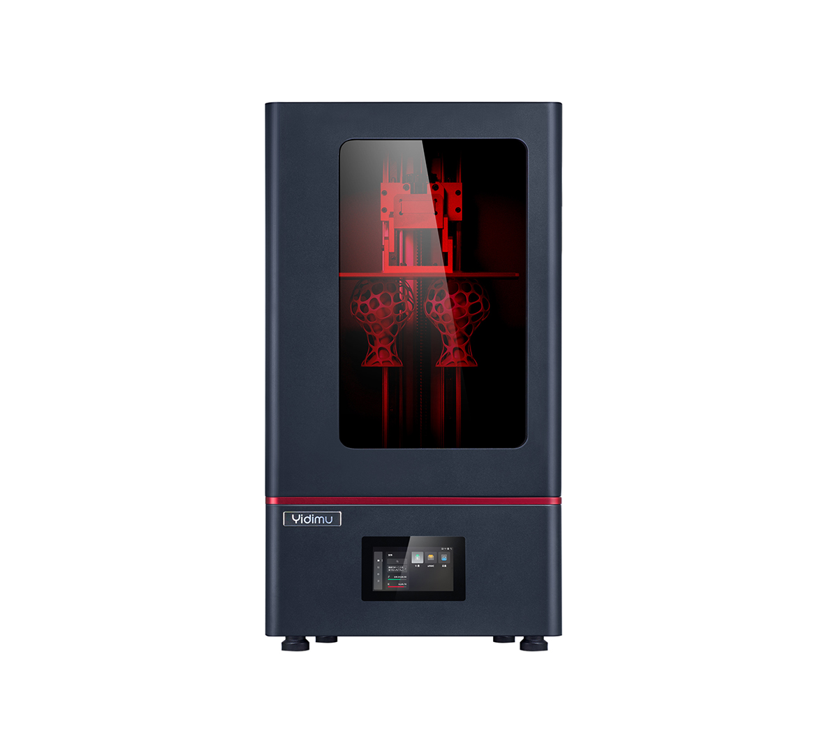
An industrial light-curing system currently presented by YIDIMU for product design, engineering models and other professional resin-printing tasks. For printed mold inserts, confirm the selected tooling resin, dimensional behavior and post-processing workflow before use.
View Eternal M1 →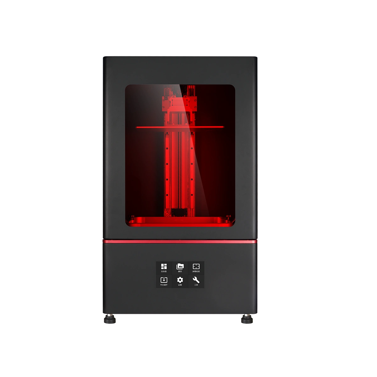
A larger industrial light-curing platform in YIDIMU’s current product range. It may be relevant when the mold block, insert set or multi-part layout needs more build area, subject to material compatibility and actual tool validation.
View Eternal M2 →Practical Evaluation Checklist
A useful project brief lets the mold designer connect the molded part, printed tool and injection process. Prepare the following before deciding whether a resin-printed mold is appropriate.
Limitations & Validation
There is no single “resin mold life” that applies to every desktop injection molding job. A small polypropylene prototype, a glass-filled engineering polymer and a deep thin-wall part can place very different demands on the same printed tool. The mold resin, cavity design, gate, venting, injected material, temperature, pressure, clamp condition, cooling, release method and inspection criteria all affect the result.
For that reason, use published rapid-tooling guidance as a starting point, not as a production guarantee. Validate the real part and record the condition of the mold after each trial stage. If dimensional stability, surface durability or safety margins are not sufficient, move to a revised printed insert, a hybrid tool with more metal support, a machined polymer tool, aluminum tooling or another process appropriate to the production requirement.
FAQ
Not automatically. A printed mold needs a resin with suitable thermal and mechanical behavior, a mold geometry designed for filling and release, complete post-processing, adequate backing or a holder when required, and testing with the intended thermoplastic and machine conditions.
Yes, draft is normally important because it reduces friction and ejection force. The required amount depends on wall depth, surface texture, molded polymer, shrink behavior and the stiffness of the printed tool.
Not necessarily. A very restrictive gate can increase filling resistance and cavity pressure. Gate design should balance fill behavior, trimming, cosmetic requirements and tool stress rather than minimizing the gate in isolation.
Many rapid-tooling setups use a rigid mold holder or metal backing to support the printed insert and distribute clamp load. Whether it is required depends on the desktop press, mold size, insert structure and loading condition.
Cycle life cannot be predicted responsibly from the words “resin printed.” It varies with tooling resin, injected polymer, temperature, pressure, cavity design, wall support, demolding, cooling and wear. Establish an expected range only after representative trials.
No. YIDIMU’s public material pages identify model and prototype applications, but they do not establish a universal injection-mold tooling rating. Tooling use requires technical-document review and project-specific validation.
Related Resources
PROJECT REVIEW
Send the part or mold file together with overall dimensions, intended thermoplastic, candidate tooling resin, quantity, desktop injection machine or mold-holder information, critical tolerances, surface requirements and the features most likely to affect filling or release. YIDIMU can use that information to discuss the resin-printing portion of the project and the sample-validation requirements without assuming a fixed production result.
Submit Project Requirements →