
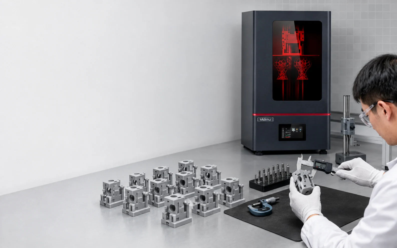
Pixel size vs print accuracy in a resin 3D printer: what is the difference?
For an LCD or MSLA resin 3D printer, pixel size is the nominal physical pitch represented by one display pixel at the build plane. It helps describe XY image sampling and possible edge granularity. Print accuracy is the closeness of the finished part to the intended CAD geometry or drawing requirement. A smaller pixel can support finer sampling, but it does not create an equal dimensional tolerance. Optical spread, light uniformity, exposure, resin response, Z motion, separation, geometry, orientation, supports, washing, complete drying, UV post-curing and measurement all influence the result. Screen specifications can shortlist equipment; representative-part testing must qualify the process.
What engineers should carry into a printer comparison
- A listed 30 μm pixel pitch does not mean every dimension will be accurate to ±0.03 mm.
- The same 8K label can represent different pixel sizes when screen dimensions or usable build areas differ.
- Rectangular pixels require separate X and Y pitch values and may make digital edge sampling orientation-dependent.
- Exposure optics and resin cure behavior determine how the digital mask becomes a cured physical edge.
- Final inspection should use the defined wash, complete-dry, UV post-cure and conditioning state.
- Critical holes, slots, datums, mating faces and thin walls should be tested in representative geometry—not inferred from a specification.
What pixel size actually tells you
In a mask-based resin printer, the LCD contains a matrix of controllable pixels. The nominal XY pixel pitch is commonly derived from the printable width and height divided by the corresponding pixel counts. It is more informative than a rounded label such as 8K, 12K or 14K because it connects the display matrix to the physical build plane.
If X and Y values are different, the printer has rectangular sampling at the build plane. A line aligned with one axis may therefore be digitized differently from the same line rotated through 90 degrees. That does not automatically make the system unsuitable, but it is a reason to test orientation-sensitive edges and features.
Pixel pitch is also not necessarily the size of the cured physical voxel. Light leaving the exposure system has a spatial distribution, and the resin responds to a dose threshold rather than to an ideal hard-edged square. Focus, collimation, mask behavior, exposure compensation and photopolymer response can make the cured boundary differ from the original digital boundary. The related guide on resin 3D printer light uniformity explains why exposure conditions should be checked across the usable platform.
| Metric | Useful meaning | What it does not prove | Better verification |
|---|---|---|---|
| Screen resolution | Number of addressable display pixels | Physical pixel size or finished-part accuracy | Read it together with usable XY build dimensions |
| Nominal XY pixel pitch | Digital sampling interval at the build plane | A universal tolerance or minimum printable feature | Print and inspect application-relevant edges and features |
| Layer thickness | Nominal slice increment in Z | Z accuracy, surface condition or total cycle time by itself | Measure stepped, vertical and angled features after processing |
| Trueness | How close a result is to the reference geometry | Repeatability across builds | Compare measured geometry with the agreed reference |
| Precision / repeatability | How closely repeated results agree with one another | That the repeated result is centered on the target | Repeat the same controlled build and measurement routine |
Why smaller pixels do not guarantee a more accurate part
A finer pixel grid can represent a smoother digital boundary, but accuracy is a system outcome. The gap between the mask image and the measured part can be introduced during exposure, layer formation, separation, support removal or post-processing. The dominant source of error may also change with geometry.
Feature resolution is not the same as dimensional tolerance
A fine engraved line may be visible even when a mating dimension misses its acceptance limit. Conversely, a larger simple block can meet its key overall dimension while showing visible pixel stepping on an angled edge. Define both functional and visual requirements. The resin 3D print quality inspection checklist provides a broader framework for dimensions, surfaces, fit and defects.
| Project question | How much pixel size helps | Evidence that should decide |
|---|---|---|
| Will small text or a fine edge be visible? | Useful for initial XY sampling comparison | Printed feature coupon in the intended resin, orientation and finish |
| Will a boss, bore or slot meet its tolerance? | Insufficient as a tolerance statement | Finished representative part measured with a suitable method |
| Will identical parts match across the platform? | Does not address spatial consistency | Positioned test parts, repeated builds and light-uniformity data |
| Will a dental model preserve arch geometry? | One input for digital sampling | Representative model after validated material-specific processing |
| Will a flexible lattice retain its intended geometry? | Only part of the edge-definition question | Controlled measurement state, lattice inspection and application test |
How to test print accuracy without confusing it with pixel size
A good accuracy study begins with the acceptance requirement and keeps the process and measurement conditions controlled. A generic calibration object can reveal broad behavior, but it should not replace the geometry that creates risk in the real project.
- Define the acceptance characteristicsIdentify datums, overall size, critical holes, slots, mating faces, wall thicknesses, clearances and cosmetic surfaces. State numerical limits only where the project actually requires them.
- Select a representative modelUse the real file where possible, or a coupon containing the same feature sizes, wall sections, angles, supports and fit relationships.
- Lock the process conditionRecord printer configuration, resin batch, material profile, layer settings, exposure, orientation, supports, platform position, environment and relevant maintenance condition.
- Test position and repetitionWhen consistency matters, place identical features at defined platform locations and repeat the build. One successful central sample cannot establish whole-platform behavior or repeatability.
- Complete material-specific post-processingWash according to the applicable TDS, SDS, IFU or formal process document. Allow parts to dry completely, then use the specified UV post-cure method. Do not invent universal wash or cure times.
- Measure in the agreed final stateUse the same instrument, datum setup, fixture, temperature condition and operator method. Flexible parts require a defined unloaded or fixtured state that does not introduce uncontrolled deformation.
- Separate bias from variationA consistent dimensional offset and a wide result spread require different responses. Consider compensation only after the process is stable and the correction is verified on representative geometry.
For complex scan-derived parts, dimensional inspection of scan-to-print parts also requires separation of scan error, mesh processing, print error and measurement uncertainty.
Why washing, complete drying and UV post-curing belong in the accuracy study
The printer stops before the part reaches its final inspection condition. Surface resin must be removed using the material-approved method. The part then needs to dry completely so liquid or solvent retained on the surface, inside holes or within cavities does not contaminate the next step or confuse measurement. UV post-curing must follow the resin-specific process because cure response and final properties vary by material.
Measure intermediate states only when the purpose is process study, and label them clearly. For acceptance, use the state defined by the drawing, laboratory procedure or application plan. A pre-cure measurement should not be compared directly with a final-cure requirement as though the two conditions were equivalent.
Dental workflows need an additional boundary: printer resolution and pixel pitch do not establish a resin's intended use, patient-contact suitability, biocompatibility or regulatory status. Review the exact resin's current documentation and validate the complete workflow for the intended task.
Three published configurations that illustrate why context matters
The current public values below describe display sampling and build geometry. They are not finished-part accuracy guarantees. Compare the system with the representative file, resin, workflow and inspection requirement.
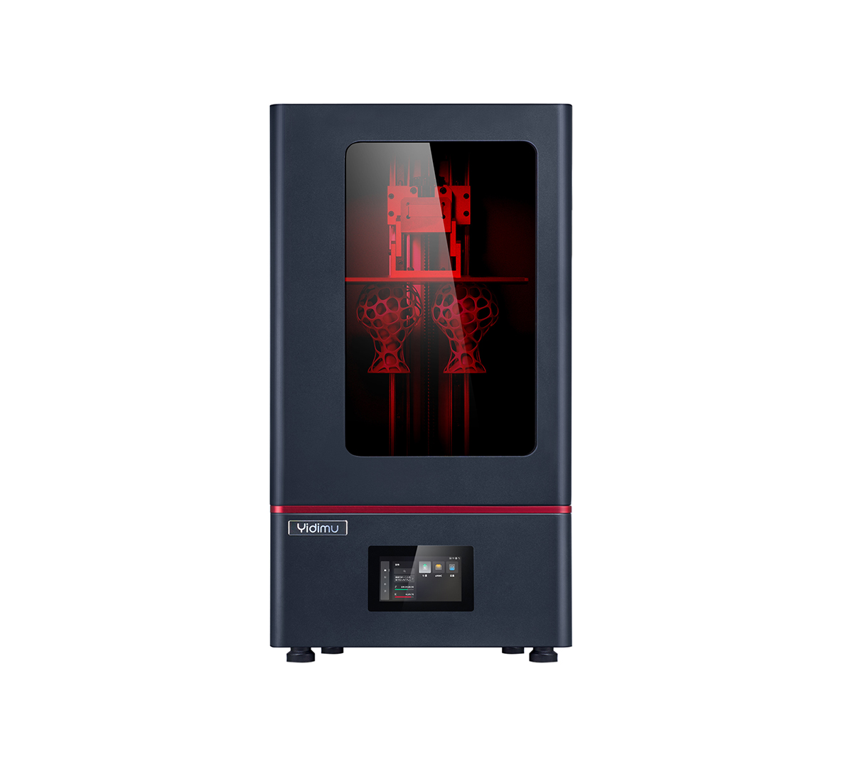
Eternal M1
13.6-inch 7K · 46 μm stated XY pixel size · 298 × 165 × 370 mm build volumeRelevant when industrial prototypes, housings, jigs, fixtures or multi-part layouts fit the published envelope and the complete process is validated.
Review Eternal M1 →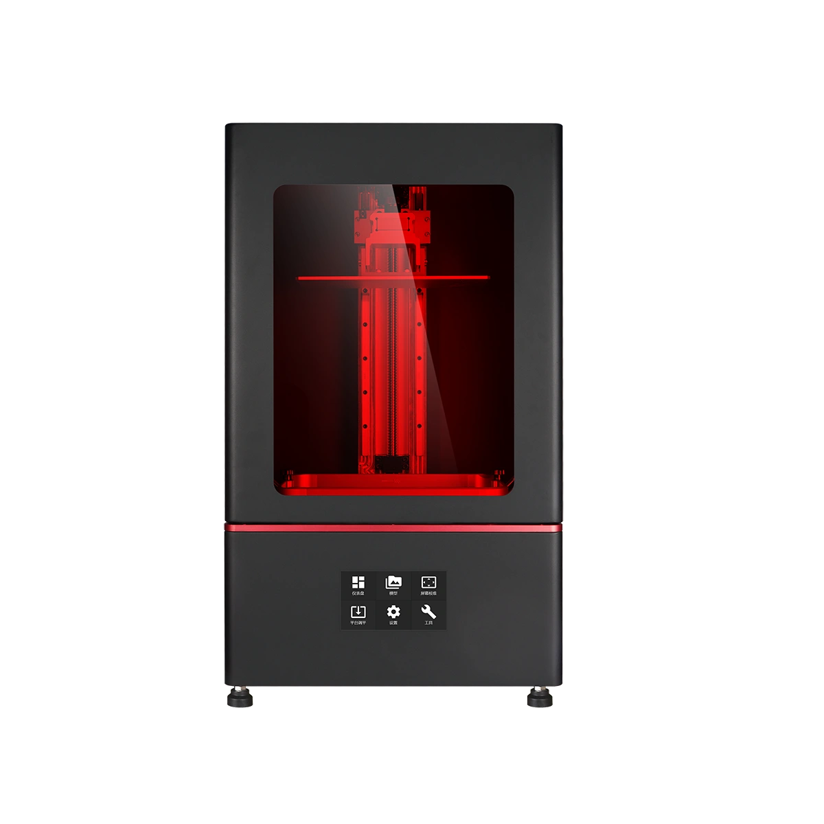
Eternal M2
16-inch 8K · approximately 46 μm XY pixel size · 353 × 198 × 400 mm listed build volumeThe similar nominal pitch to M1 does not make the systems interchangeable; build geometry, part fit, supports and downstream handling still shape the decision.
Review Eternal M2 →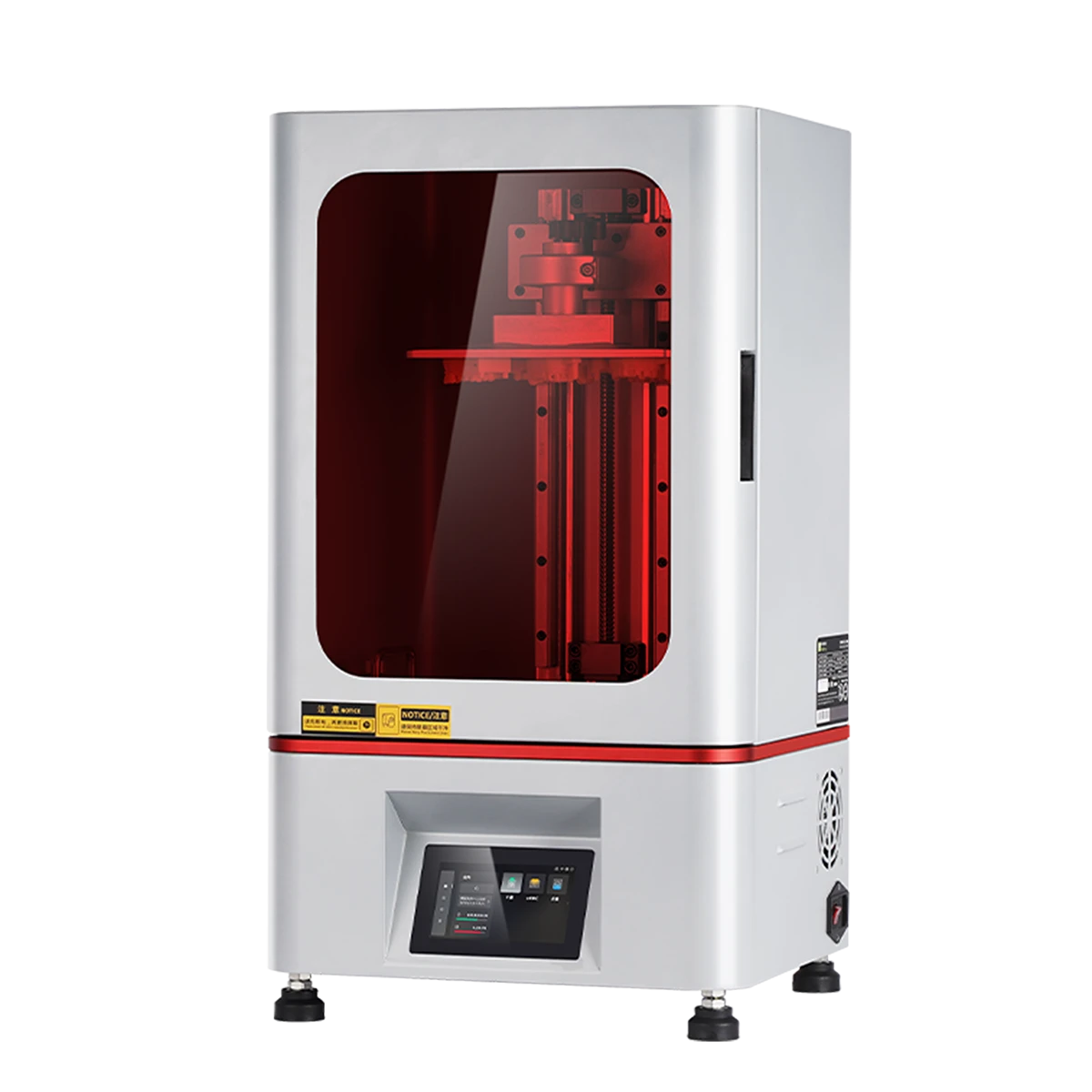
Eternal D1
10.1-inch 14K · X 16.8 / Y 24.8 μm nominal pitch · 223 × 126 × 290 mm build volumeThe non-square pitch shows why both axes should be stated. Dental model suitability still depends on the file, resin documentation, post-processing and inspection.
Review Eternal D1 →Information to prepare before sample validation or equipment selection
- Representative STL, OBJ or other agreed model file, plus a drawing when tolerances matter
- Overall dimensions and the supported, oriented bounding size
- Intended use and what the physical part must prove
- Critical datums, holes, slots, walls, pins, edges and mating surfaces
- Required material behavior and the exact resin documentation available
- Quantity per build, repeated-build requirement and accepted output target
- Visible surfaces, texture, support-mark and finishing expectations
- Fit, clearance and tolerance requirements tied to specific features
- Required washing, complete drying, UV post-curing and conditioning state
- Measurement instrument, datum setup, fixture, sample count and reporting format
A specification table cannot qualify your production process
Pixel size, screen resolution, layer thickness and build volume are useful comparison inputs, but they cannot predict every geometry, resin or acceptance condition. Actual results vary with equipment condition, material, model, layer settings, orientation, supports, exposure, environment, washing, complete drying, UV post-curing, finishing and measurement.
Use representative parts and written acceptance criteria before selecting equipment for a demanding project or extending a setup into repeated production. For material handling and processing, follow the applicable TDS, SDS, IFU and current formal technical documents.
Pixel size and resin print accuracy questions
Does a 20 μm pixel size mean ±0.02 mm print accuracy?
No. The 20 μm value describes nominal XY sampling, not a bilateral dimensional tolerance. Finished dimensions depend on the entire equipment, resin, geometry, build and post-processing system.
Is a 14K resin printer always more accurate than an 8K printer?
No. The K label is a display pixel-count category. Compare physical X and Y pitch, usable build area, optics, process control and measured representative parts.
What is the difference between pixel size and layer height?
Pixel size describes nominal sampling in the XY build plane. Layer height is the nominal slice increment in Z. Neither value alone establishes three-dimensional accuracy.
Can a printer reliably produce a feature smaller than one pixel?
Do not assume it. Optical exposure, grayscale or compensation and resin response can create boundaries that are not simple pixel-sized blocks, but reliable feature reproduction must be demonstrated with the intended geometry and process.
When should a resin print be measured?
For final acceptance, measure it in the agreed finished state after required washing, complete drying, UV post-curing and specified finishing or conditioning. Record any intermediate measurements separately.
What should be included in a printer accuracy sample test?
Include representative geometry, critical dimensions, mating features, important surfaces, intended resin, production orientation, support strategy, complete post-processing and the measurement plan. Repeat and platform-position tests may be needed when consistency matters.
Submit the part requirement—not only the pixel specification
Share the model file, overall dimensions, intended application, material requirement, quantity, critical features, surface expectations, fit or tolerance requirements, post-processing condition and planned inspection method. YIDIMU can use those inputs to discuss a relevant printer, resin direction and representative validation path without treating a specification table as proof of the final result.
Submit Your Model & Requirements →