
Resin Print Dimensional Accuracy Troubleshooting
Most resin print dimensional problems follow a recognizable pattern: a constant offset on every edge, a scale error that grows with part size, an error that shows up only in Z, or a distortion confined to one area, one build position or one stage of post-processing. Each pattern points to a different cause. Identify which one you have before you touch exposure settings or apply compensation, or you'll end up correcting the wrong thing.
The method below applies to vat photopolymerization in general: masked LCD (MSLA), DLP and laser SLA. How light spreads at a feature edge differs between these systems, but the diagnostic logic doesn't. Absolute values depend on the resin, layer height, exposure, geometry and post-cure, so treat this as a way to find the cause, not a set of numbers to copy.
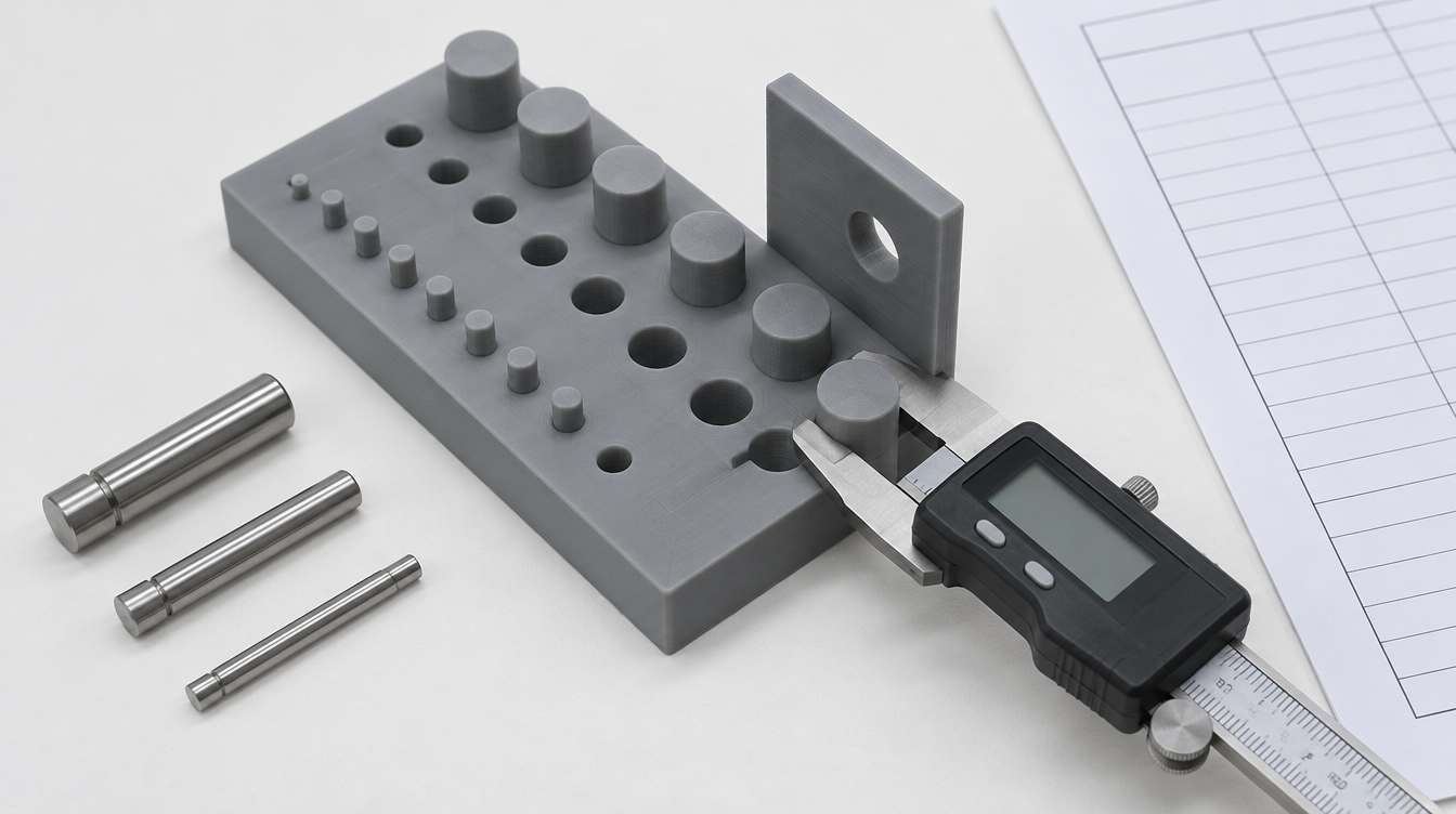
Describe the error before you diagnose it
"The part is too big" can't be fixed. "The 8 mm bore is undersize in Z, measured with a pin gauge after full post-cure" can. Before changing anything, write down which feature is out, along which axis, whether it's oversize or undersize, at what point in the workflow it was measured, and with what instrument.
Always check an outer feature and an inner feature together. A block and a hole respond to the same cause in opposite directions. If extra resin cures at every edge, the block grows and the hole shrinks. If you only measure holes, you can easily mistake edge growth for shrinkage and push the correction the wrong way.
Which error pattern do you have?
Most dimensional complaints fit one of the rows below. The first check in each row is the cheapest way to confirm the pattern before you commit to a fix.
| Pattern | What the measurements show | Most likely causes | First check |
|---|---|---|---|
| Constant edge offset | Outer features oversize, holes and slots undersize, by roughly the same amount at every nominal size | Overexposure, light spreading past the intended edge, anti-aliasing or blur settings, beam offset on laser systems | Exposure calibration print with the same resin and layer height |
| Scale error | Deviation grows in proportion to the dimension; long features are off more than short ones | Polymerization and post-cure shrinkage, a scale or compensation factor in the slicer, unit or export scaling | Measure a long and a short feature on the same part along the same axis |
| Z-only error | Height oversize, the first few millimeters wider than the rest, downward-facing surfaces too thick | Bottom-layer exposure, cure depth exceeding layer thickness under overhangs, build platform zero | Measure height above the bottom and transition layers separately |
| Local distortion | One face bowed, one corner out, error concentrated near supports or thin sections | Support placement, peel forces, unsupported spans, residual stress, sagging during heated post-cure | Print the same feature in a second orientation or support layout |
| Position-dependent | The same part measures differently depending on where it sat on the platform | Light uniformity across the exposure area, platform flatness, local wear on the vat film | Identical coupons at the center and corners of one build |
| Time-dependent | Dimensions change between wash, cure and the next day | Solvent uptake during washing, incomplete drying, ongoing cure shrinkage, part temperature | Measure the same feature at fixed points in the workflow |
| Build-to-build drift | The same file and settings give different results on different days | Resin temperature, settled or aged resin, film or light-source condition, uncontrolled process steps | Repeat one build and look at the spread, not the average |
The last row is a repeatability problem rather than an accuracy problem. That distinction matters because compensation can correct a stable bias but can't fix scatter. If you need the vocabulary straight, see 3D printing accuracy vs precision.
Run a size-series test before changing settings
A single calibration cube can't separate offset from scale, because one size gives you one point. A size series gives you a line, and the shape of that line tells you which correction applies.
Model a coupon with external blocks or pins and internal holes or slots at several nominal sizes that span the range of your real parts. Include features along X, Y and Z, plus one hole whose axis runs parallel to the build platform.
Print it with the production resin, layer height, orientation and support strategy, at the platform position you actually use.
Wash, dry and post-cure it exactly as production parts are processed. Let it return to room temperature.
Measure every feature with the instrument you use for acceptance. Pin gauges are more reliable than calipers for small holes.
Plot measured minus nominal against nominal size, separately for outer and inner features and for each axis.
A flat line that sits away from zero, with outer features positive and inner features negative, is an edge offset. A sloped line is a scale error. Points that scatter without a trend mean the measurement or the process isn't stable enough to correct yet. Print the coupon at least twice before you act on a slope; the difference between two builds can be as large as the correction you were about to make.
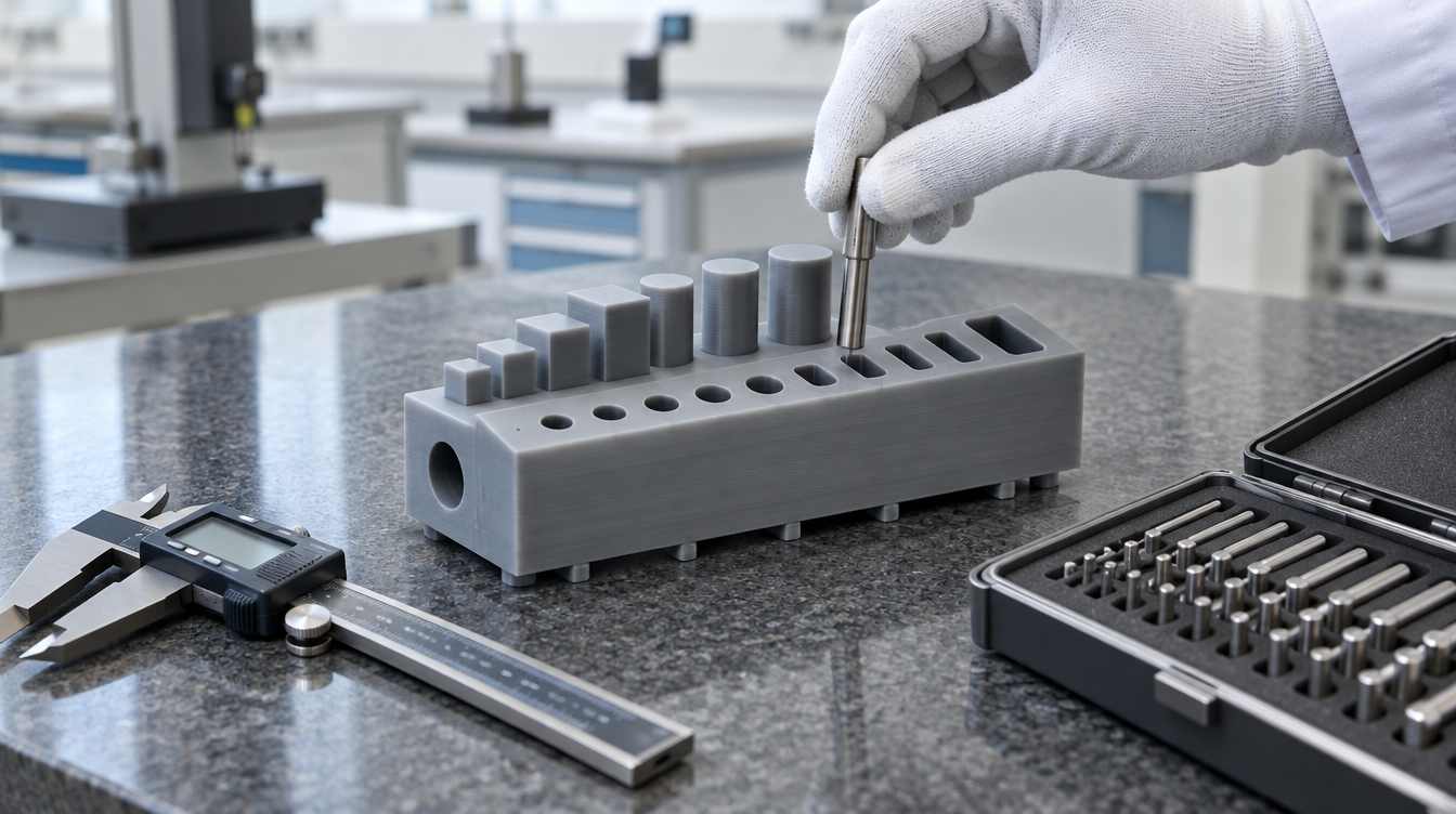
Fix causes in order: exposure, geometry, post-processing, then compensation
The order matters because each step changes the result of the next. Compensation derived before exposure is settled has to be redone the moment exposure changes.
Exposure and edge growth
Overexposure cures resin beyond the boundary of the intended cross-section. On MSLA printers, light from each open pixel spreads slightly into its neighbors, and anti-aliasing or image blur settings shift where the effective edge lands. Laser systems have the equivalent problem through spot size and beam offset. Underexposure does the opposite, and it also leaves fine features weak or missing.
Calibrate exposure for the specific resin and layer height first. If a hole is still undersize after exposure is correct, don't keep cutting exposure to open it up. You'll gain hole diameter and lose layer bonding. That's the point where compensation becomes the right tool.
Bottom layers and Z height
The first layers get much longer exposure so the part sticks to the platform. Those layers spread outward, which is why the base of a part often measures wider than the rest. Measure critical heights from above the transition layers, add a small chamfer at the base of parts printed directly on the platform, or raise them on supports.
Downward-facing surfaces have their own Z error. When cure depth exceeds layer thickness, light reaching through the current layer cures extra resin underneath overhangs. Limaye and Rosen described this print-through effect in mask projection stereolithography and proposed removing a compensation zone from the underside of the model. You'll see it most clearly in a hole whose axis runs parallel to the platform: the top of the bore is an overhang, it collects extra cured material, and the hole comes out short in Z and slightly oval.
Orientation, supports and peel forces
Support contacts leave nubs, and a nub on a measured face reads as oversize. Too few supports let thin sections deflect under peel forces, and that deflection is cured in place. Large flat cross-sections increase peel load and make it worse. Keep critical datums and mating faces away from support contacts, tilt large flat areas, and check whether the error moves when the support layout changes. For large parts, warping has its own set of causes, covered in how to print large resin parts without warping.
Washing, drying and post-curing
Long solvent soaks can be absorbed into the green part and change its dimensions until the solvent leaves. Post-curing continues polymerization, and the part can shrink further as it does. Heated post-cure also softens the part, so a thin or poorly supported section can sag. A study of SLA-printed dental appliance samples found that post-curing conditions significantly affected their dimensional accuracy.
Follow the resin manufacturer's wash and cure guidance, and then keep wash time, drying and cure recipe fixed. A measurement taken straight out of the wash and another taken after cure are measurements of two different parts.
Compensate only a stable, known bias
Once the pattern holds across repeated builds, apply the matching correction: XY offset or hole compensation for a constant edge offset, a per-axis scale factor for a scale error, and model changes such as a compensation zone or base chamfer for Z effects. Record the resin, batch, layer height, exposure and post-cure recipe alongside the correction. Change any of them and the compensation needs to be checked again.
When results drift from build to build
If the size-series test gives different answers on different days, look at what changes between builds rather than at the settings. Resin temperature affects viscosity and reactivity, so a cold morning build and an afternoon build won't cure identically. Filled and pigmented resins settle and need mixing. Vat film wear and contamination on optical surfaces change how much light reaches the resin, and light-source output can change over its service life. Check the printer's specified operating temperature range and keep the room inside it.
The routine fix is boring but effective: print the same coupon on a schedule, measure it the same way, and treat a shift in the result as a maintenance signal before it becomes a rejected batch. The resin 3D printer troubleshooting guide covers the film, exposure and Z-axis checks in more detail.
Problems that aren't printing problems
Some dimensional failures are introduced before or after the printer does anything.
STL export resolution. A coarse tessellation turns a hole into a polygon. The measured diameter then depends on whether the pin touches a flat or a vertex. Re-export with a tighter chord tolerance.
Design intent. A zero-clearance fit in CAD won't assemble from any process. Printed mating parts need clearance designed in, and the tolerance stack has to be checked like any other process.
Measurement method. Caliper jaw pressure deforms thin walls and flexible parts. Warm parts read differently from parts at room temperature. Measuring across a support nub or layer step adds material that isn't really there.
Scan comparison alignment. A best-fit alignment spreads a systematic bias across the whole part, so an edge offset can look like small random deviation. Align to the functional datums instead.
For how to read a deviation result once you have it, including why one number doesn't establish accuracy or repeatability, see 3D printing dimensional deviation.
Checklist before you change a setting
The out-of-spec feature, axis and direction (oversize or undersize) are recorded.
Outer and inner features were both measured.
Measurements were taken at the same point in the workflow, at room temperature, with the acceptance instrument.
The size-series coupon was printed at least twice.
Exposure is calibrated for this resin and layer height.
Critical faces carry no support contacts.
Wash time, drying and post-cure recipe are fixed.
Any compensation is recorded with the resin batch, layer height, exposure and cure recipe it was derived for.
If the pattern points to a limit you can't resolve on your current setup, send YIDIMU the CAD file, the dimensions that control acceptance and the tolerance you need. The applications team can review the part, resin and workflow and print a representative sample before you commit to a process.