
Resin 3D Print Supports: Placement, Removal & Troubleshooting
Resin 3D print supports are temporary structures that hold a model in position and stabilize unsupported features during printing. They help prevent detached layers, missing details, deformation, and print failures in SLA, DLP, and LCD/MSLA resin printing.
Good support design requires more than adding enough pillars beneath a model. The goal is to maintain print stability while minimizing contact damage, resin consumption, and post-processing work. This is especially important for engineering prototypes, dental models, flexible structures, and parts with critical surface requirements.
What Are Supports in Resin 3D Printing?
Support structures connect a printed part to the build platform or to other supported regions of the model.
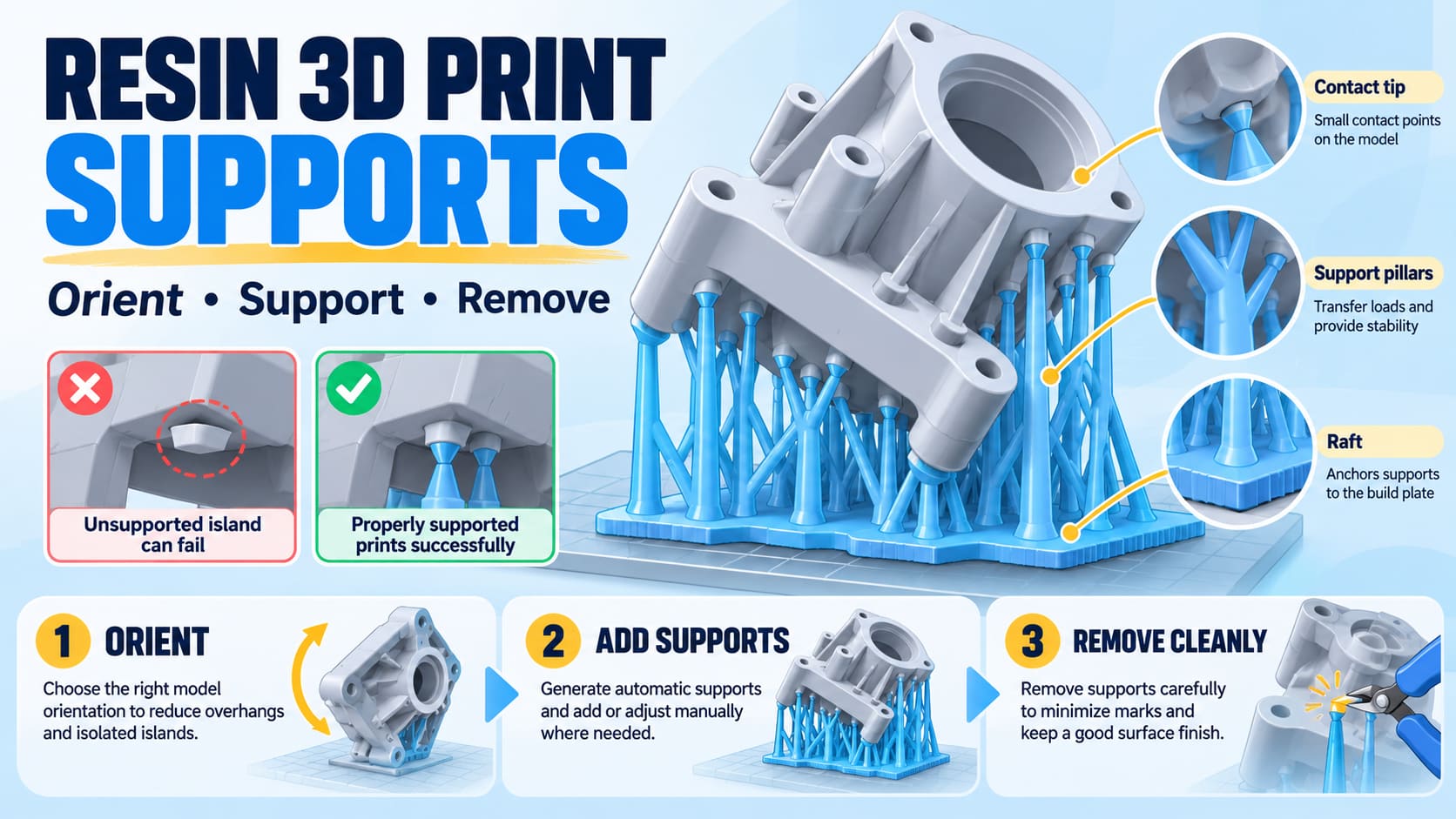
In many resin printing workflows, they consist of three main elements:
Raft or base: Anchors the support structure to the build platform.
Support pillars and branches: Transfer loads between the model and its supporting base.
Contact points or tips: Connect the supports to the actual printed geometry.
Unlike conventional FDM supports, which may use a separate support material, resin printing supports are generally produced from the same photopolymer resin as the model.
Supports perform several functions:
Hold isolated features in position when they first appear during printing.
Stabilize overhangs, thin walls, and projecting geometry.
Help resist forces generated during layer separation.
Reduce unwanted movement or deformation during the build.
Provide a controlled connection between the model and build platform.
However, more supports do not automatically mean better prints. Excessive support contact can damage surfaces, obstruct cleaning, and increase finishing time.
When Does a Resin 3D Print Need Supports?
A model usually needs supports when portions of its geometry cannot be built reliably from an existing supported layer or directly from the build platform.
Common examples include:
| Model feature | Why support may be necessary |
|---|---|
| Overhangs | Material extends beyond the adequately supported geometry beneath it. |
| Isolated islands | A new section appears in a layer without a reliable connection to previously cured material. |
| Thin walls | Slender geometry can bend or distort during printing and release. |
| Long projecting features | Mechanical loading can cause movement or detachment. |
| Heavy or broad sections | Larger cured regions can impose greater loads on the support structure. |
| Complex dental and industrial models | Detailed or functionally important features require controlled orientation and support placement. |
Can resin prints be made without supports?
Yes. Some parts with suitable flat surfaces and favorable geometry can be printed directly on the build platform.
Direct printing can reduce support material and removal work, but it also introduces considerations such as initial-layer dimensional changes, platform-contact surface quality, and removal forces.
A support-free orientation should be selected because it works for the actual geometry, not simply because it reduces material consumption.
How to Add Supports to Resin 3D Prints
A reliable support workflow begins with the model's orientation rather than the slicer's automatic support button.
Step 1: Choose the right model orientation
Orientation influences release forces, support placement, surface finish, dimensional behavior, and total build height.
Before generating supports, identify:
Critical mating and reference surfaces.
Visible surfaces where support marks are undesirable.
Thin walls, holes, channels, and small features.
Large cross-sectional areas and abrupt changes between layers.
Cavities that could trap resin or create suction-related loading.
Orient the model so that sensitive surfaces face away from support contacts where practical.
Tilting a part can reduce certain unsupported regions and abrupt cross-sectional changes. However, there is no universal printing angle that works for every resin, geometry, and machine.
For hollow models, also evaluate drainage and pressure relief. Increasing support strength alone does not resolve a poorly oriented cavity that creates suction during layer separation.
Step 2: Generate automatic supports
Most professional resin slicing applications include automatic support generation.
Software such as CHITUBOX provides controls for support contact geometry, pillar dimensions, contact spacing, raft design, and other support parameters.
Automatic generation offers a useful starting point, especially for models with numerous small features.
However, automatically generated supports should always be reviewed before printing.
Pay particular attention to isolated islands, leading edges, heavy sections, and areas where supports may be difficult to remove.
Step 3: Add manual supports where necessary
Manual support editing is valuable when automated placement leaves critical regions insufficiently supported or places contacts on important surfaces.
Consider adding or modifying supports around:
The earliest isolated sections of a model.
Long edges that begin printing without sufficient restraint.
Thin projecting features.
Large features connected through a narrow section.
Regions that visibly failed in a previous print.
Avoid attaching strong supports directly to fragile details when a less sensitive support location is available.
Step 4: Choose an appropriate support strength
Resin slicers commonly offer light, medium, and heavy support categories, although their exact geometry and settings differ between software versions.
| Support approach | Typical application | Main consideration |
|---|---|---|
| Light supports | Small details and delicate geometry | Small contact areas may detach under higher loads. |
| Medium supports | General-purpose models and moderately sized features | Balance contact strength against removal damage. |
| Heavy supports | Larger or more heavily loaded regions | Stronger connections can create larger removal marks. |
| Reinforced or braced supports | Tall support structures and geometries requiring additional stability | Added material and contact complexity can increase finishing work. |
These are application categories, not universal parameter specifications.
Contact diameter, penetration depth, support spacing, pillar thickness, and bracing should be selected using the printer and resin's validated workflow.
Reducing contact diameter can improve appearance, but it may also weaken the connection. Increasing support density may improve local restraint, but it cannot compensate for every orientation or exposure problem.
Step 5: Inspect the sliced layers
Support placement should be checked in the actual sliced geometry.
Scroll through the layers from the beginning of the build and examine when each feature first appears.
Ask three questions:
Does every new isolated feature have a reliable support connection?
Is the growing model adequately restrained as its cross-sectional area changes?
Are any cavities or narrow regions likely to create cleaning, drainage, or separation problems?
A model can look adequately supported in the 3D preview while still containing isolated features or difficult layer transitions.
Step 6: Save the support strategy
For engineering validation or repeat production, save the approved orientation, support settings, and slicing file.
A successful model should not depend on someone recreating the same support layout manually for every build.
Resin 3D Print Supports Keep Failing: What Should You Check?
When a resin print fails, examine the location of the failure before increasing exposure or support density.
The physical condition of the supports can help distinguish a contact problem from a support-shaft, platform, geometry, or machine-related problem.
| Observed problem | Possible causes | First checks |
|---|---|---|
| Raft detaches from the build platform | Platform adhesion or initial-layer process problem | Platform condition, setup, resin profile, initial layers |
| Pillars remain but the model detaches | Weak model contact, excessive release load, poor orientation | Tip geometry, contact placement, unsupported regions |
| Support pillars break | Inadequate pillar strength, excessive unsupported length, mechanical loading | Pillar dimensions, bracing, model cross-section |
| Small details are missing | Unsupported islands, fragile geometry, slicing problems | Layer preview, isolated features, local supports |
| Part bends or warps | Orientation, insufficient restraint, resin behavior, post-processing | Support layout, wall geometry, material workflow |
| Large support scars appear | Contact size, depth, placement, or removal technique | Contact location, finishing allowance, removal method |
Diagnose the failure at the connection point
Consider an industrial housing that repeatedly detaches from the tips of its support pillars.
The raft remains attached to the platform, and most pillars are still present.
This pattern suggests that the first investigation should focus on the model-to-support connection and the loads acting on it.
Useful checks include:
Whether the first model sections are adequately supported.
Whether contact points are concentrated on a small area.
Whether the orientation creates unnecessarily large layer sections.
Whether the selected resin profile is appropriate.
Whether the supports are properly represented in the sliced file.
Increasing every support dimension may improve attachment but could create unnecessary removal damage.
A more targeted correction is to reinforce the critical connection while reviewing the model orientation.
If instead the entire raft detaches, changing only the contact tips is unlikely to solve the underlying issue.
When should you stop changing supports?
If different models fail repeatedly in the same build-area location, or the printer shows abnormal motion, exposure behavior, or mechanical noise, investigate the equipment and process rather than continually adding supports.
Inspect accessible components according to the machine's instructions. Stop operation and contact technical support if hardware damage or unsafe operation is suspected.
For additional symptom-based guidance, see the YIDIMU Resin 3D Printer Troubleshooting Guide.
How to Reduce Support Marks on Resin Prints
Support marks result from the physical connection between the temporary support structure and the finished model.
They may appear as small protrusions, depressions, or locally damaged surfaces after support removal.
The most effective way to reduce them is to plan the contact locations before printing.
Protect critical surfaces
For industrial components, keep supports away from locating faces, sealing areas, critical holes, datum surfaces, and precision assembly interfaces whenever practical.
For appearance prototypes, place support contacts on hidden or less visible surfaces.
A support strategy that produces a successful print may still be unacceptable if its removal damages a functional surface.
Use smaller contacts selectively
Smaller contact points can reduce visible marks, but decreasing their size everywhere increases the risk of detachment.
Use appropriately sized contacts based on local loading and the material's behavior.
Where surface requirements are especially strict, consider whether a sacrificial feature, a different orientation, or a revised part design would provide a more reliable finishing strategy.
Include finishing in the design
Some parts will require trimming, sanding, polishing, filling, or coating.
Plan sufficient access for these operations and verify that material removal will not compromise a critical dimension.
For customer-facing models, see Resin 3D Printing for Appearance Prototypes.
Should Resin Supports Be Removed Before or After Curing?
There is no single correct removal stage for every resin.
Removing supports before final UV post-curing may make some contacts easier to separate. However, partially processed parts can be delicate, and early removal may allow thin or unsupported geometry to distort.
Leaving supports in place through post-curing can help retain geometry in some workflows, but contacts may become more difficult to remove afterward.
Follow the material manufacturer's processing instructions and validate the removal sequence for the actual part.
A controlled post-processing procedure typically includes:
Remove the printed part using the correct machine procedure.
Wash it with a cleaning method compatible with the resin.
Allow the part to dry completely.
Remove supports at the appropriate stage for that material and geometry.
Apply the specified UV post-curing procedure.
Finish the support-contact regions and inspect the part.
The order of support removal and final curing may change according to the approved material workflow.
When cutting supports, stabilize the model, work progressively, and avoid pulling entire support assemblies away from delicate features.
Use suitable cutters or precision tools to separate difficult contacts without tearing the model surface.
Uncured resin and cleaning solvents require appropriate handling. Follow the resin's safety data sheet, provide suitable ventilation, and use compatible protective gloves and eye protection. Sanding operations also require dust-exposure controls.
Support Design for Industrial, Dental, and Flexible Resin Printing
Although the underlying support principles are similar, the appropriate strategy depends on the application.
Industrial prototypes and functional parts
Engineering parts often have surfaces that control assembly, alignment, sealing, or dimensional inspection.
Support placement should protect these regions while adequately restraining the geometry during printing.
For larger industrial parts, the load distribution across the support structure becomes increasingly important.
An orientation that works for a small display model may not be appropriate for a larger housing with broad surfaces and thin sections.
Dental models
Dental resin printing requires particular attention to anatomical details, reference surfaces, and model fit.
Support placement should avoid damaging functional or measurement-critical surfaces.
Material compatibility, validated processing instructions, cleaning, curing, and dimensional inspection remain necessary.
A successful print does not independently establish clinical suitability or dimensional acceptance.
Flexible and elastomer parts
Flexible resins can behave differently from rigid photopolymers during separation, washing, support removal, and final curing.
For flexible lattices, cushioning structures, and footwear components, consider:
Whether thin struts deform under local printing loads.
Whether support contacts can be removed without tearing the lattice.
Whether internal regions remain accessible for cleaning.
Whether support density interferes with post-processing.
Whether the final geometry requires additional restraint during handling or curing.
A rigid-resin support profile should not automatically be transferred to an elastomer material.
The support layout must be assessed together with the selected resin, geometry, machine, and processing instructions.
A Practical Method to Validate Your Support Settings
For professional printing, the objective is not just to complete one successful model. It is to establish a support strategy that can produce acceptable parts consistently.
A useful validation method is to compare two controlled support layouts for the same representative CAD model.
Layout A: Use the current approved or baseline support arrangement.
Layout B: Change one clearly defined aspect of the support strategy, such as the location of contacts on a critical edge or the reinforcement of a heavily loaded region.
Keep the other relevant inputs consistent:
Printer and resin grade.
Model revision and build orientation, unless orientation is the variable being tested.
Exposure and machine profile.
Washing, drying, and post-curing procedure.
Inspection method.
Evaluate the results using four criteria.
| Evaluation criterion | What to record |
|---|---|
| Print integrity | Missing features, detached supports, layer separation, distortion |
| Dimensional condition | Measured deviation at defined critical features |
| Surface quality | Support marks, visible defects, finishing damage |
| Removal workload | Support removal difficulty and operator time |
Do not select a support strategy solely because it uses less resin.
A layout that saves support material but increases rejected parts or damages critical surfaces may be more expensive in practice.
Once an acceptable arrangement is identified, record the slicer profile and process revision. Repeat representative builds when production consistency is a requirement.
Frequently Asked Questions
Do all resin 3D prints need supports?
No. Some geometries can be printed directly on the build platform without additional support structures. Parts with isolated features, overhangs, or difficult release conditions may require supports to print reliably.
Are automatic resin supports reliable?
Automatic supports provide a useful starting point, but they are not a substitute for reviewing model orientation, islands, critical surfaces, and the sliced layers. Manual adjustments may be necessary for demanding geometry.
Why do resin prints fail even with many supports?
Support quantity is only one variable. Failures may also involve contact strength, orientation, release forces, exposure settings, resin condition, platform adhesion, vat condition, or machine operation. The location and pattern of failure should guide troubleshooting.
How do I remove supports without damaging a resin print?
Follow the material-specific cleaning and curing sequence, support the model during removal, and cut difficult contacts progressively. Avoid pulling large support sections away from delicate geometry. Remaining marks may need controlled finishing.
Evaluate Resin Supports as Part of the Complete Printing Process
Resin 3D print supports influence more than whether a model stays attached during printing. They also affect surface quality, dimensional condition, material consumption, finishing work, and production consistency.
The appropriate solution combines model orientation, contact placement, support strength, a validated resin profile, and controlled post-processing.
YIDIMU provides resin 3D printing equipment, photopolymer materials, and application support for industrial prototypes, flexible components, and dental workflows.
If you are evaluating a part with difficult geometry, critical surfaces, or repeated support failures, submit your model and application requirements for a printer, material, and process discussion.
References
CHITUBOX — Configure Support Parameters
https://docs.chitubox.com/en-US/chitubox-basic/latest/ui-and-features/configure-support-parametersPrusa Research — Tree Supports for SLA Printing
https://help.prusa3d.com/article/tree-supports_1515CDC/NIOSH — Safe Desktop Vat Photopolymerization 3-D Printing
https://www.cdc.gov/niosh/media/pdfs/2025/01/Safe-3D-Printing.pdf