
Process Validation · Dimensional Inspection
3D Printing Dimensional Deviation: What Does the Result Really Tell You?
A dimensional difference between CAD and a finished resin print is useful evidence, but it is not automatically a printer-accuracy result. The engineering value comes from identifying the pattern behind the deviation: systematic bias, random variation, geometry-dependent error, build-position effects or dimensional change introduced during post-processing.
- A single dimensional error does not establish accuracy, repeatability or process capability.
- The sign, location, feature type and spread of the deviation often matter more than one headline number.
- Finished-part inspection should use a controlled and repeatable post-processing condition.
- Pixel size, screen resolution and layer height cannot be converted directly into finished-part tolerance.
- Corrective action should follow the deviation pattern rather than applying global compensation by default.
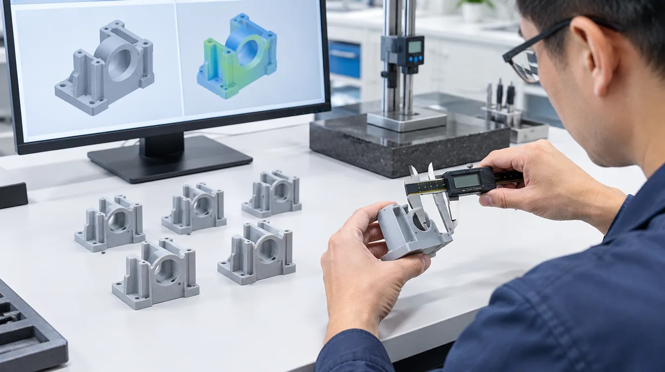
What does 3D printing dimensional deviation actually tell you?
3D printing dimensional deviation tells you how far a measured feature on a particular printed part is from its defined nominal value under a particular process and inspection condition. By itself, it does not prove printer accuracy, repeatability or production capability.
The result becomes more informative when you compare the direction and magnitude of the error across several features, parts, build positions and print jobs. A consistent offset suggests a different problem from measurements that scatter randomly around the nominal value. A hole that repeatedly prints undersize also tells a different story from an entire part that is uniformly scaled.
For resin printing, washing, complete drying, support removal, UV post-curing, geometry and measurement timing must also be considered before the deviation is interpreted.
Key takeaways for engineering evaluation
- Deviation is an observation, not a tolerance. Tolerance is the allowable range defined by the design or application.
- A small average error can hide large variation. Positive and negative deviations may cancel when averaged.
- Feature type matters. External dimensions, holes, slots, walls and unsupported surfaces do not necessarily respond in the same way.
- Post-processing is part of the dimensional process. Final acceptance should normally refer to the finished condition required by the application.
- Compensation should follow diagnosis. Scaling a CAD file or applying XY compensation before identifying the source of variation can improve one feature while making another worse.
- Production decisions require repeated evidence. One successful sample cannot establish repeatability or process capability.
Start with the simplest quantity: measured minus nominal
For a defined linear dimension, dimensional deviation can be expressed simply as:
A nominal 40.00 mm feature measured at 40.12 mm has a positive deviation of 0.12 mm. The same feature measured at 39.88 mm has a negative deviation of 0.12 mm.
That calculation is easy. Interpretation is where engineering judgement begins.
Suppose five parts produce deviations of +0.10, +0.12, +0.11, +0.09 and +0.11 mm on the same controlled feature. The process is showing a directional bias with relatively little part-to-part spread. A different set of −0.18, +0.15, −0.11, +0.17 and −0.03 mm might average close to zero, yet the variation would be much less attractive for an assembly feature.
Looking only at the average could therefore lead to the wrong decision. Direction, spread and repeatability must be considered together.
Deviation, accuracy, repeatability and tolerance are not interchangeable
| Term | Engineering meaning | What it does not prove |
|---|---|---|
| Dimensional deviation | Difference between a measured feature and its defined nominal value. | Whether the overall process is stable or capable. |
| Accuracy / trueness | How closely results agree with the intended or reference value. | How tightly repeated results cluster. |
| Precision | How closely repeated measurements or results agree with each other. | Whether they are centered on the nominal value. |
| Repeatability | Variation when the process is repeated under defined, substantially unchanged conditions. | Performance under different machines, operators or broader conditions. |
| Reproducibility | Agreement when relevant conditions change, such as equipment, operator or location, depending on the study. | Universal performance for every part geometry. |
| Tolerance | The permitted dimensional variation established by the drawing, fit or application requirement. | The actual variation the printing process produces. |
| XY pixel size | A characteristic of the imaging system in masked resin printing. | Finished-part dimensional accuracy or guaranteed tolerance. |
| Layer height | The nominal vertical increment used during layer generation. | Z-axis dimensional accuracy. |
This distinction matters during equipment procurement. A finer pixel size or higher display resolution may affect how the exposure image is represented, but the printed dimension still passes through the optical system, resin response, mechanical motion, separation process, supports and post-processing workflow before it reaches an inspection instrument.
For a broader discussion of why nominal display specifications should not be treated as finished-part performance, the 8K vs 12K vs 16K resin printer guide examines that distinction in more detail.
The pattern behind the deviation usually matters more than the isolated number
| Observed pattern | What it may indicate | Useful next check |
|---|---|---|
| Most repeated features shift in the same direction by a similar amount | Possible systematic bias in the controlled workflow | Repeat the build, confirm measurement method, then investigate calibration, exposure, resin behavior and compensation strategy. |
| Average deviation is near zero but results have wide scatter | Variation is being hidden by the average | Review repeatability across parts and builds before attempting nominal compensation. |
| Center samples differ from edge or corner samples | Possible spatial process effect | Map identical test features across the platform and investigate exposure, platform condition, release behavior and other location-dependent variables. |
| External dimensions are acceptable but holes are consistently undersize | Feature-specific process behavior rather than simple global scaling | Compare several internal feature sizes and review exposure, geometry, orientation and measurement access. |
| A part changes noticeably between pre-cure and finished inspection | Post-processing is contributing to the final geometry | Control washing, complete drying, support removal, curing and measurement timing. |
| Deviation changes when orientation changes | Geometry, support and process direction are interacting | Repeat representative orientations while keeping material and downstream processing constant. |
Spatial patterns deserve particular attention on resin systems. If the same geometry repeatedly behaves differently at specific platform locations, the investigation should not jump immediately to CAD compensation. Exposure-field behavior is one possible variable, but so are platform condition, mechanics, release behavior, resin condition and downstream processing. The resin 3D printer light-uniformity guide explains how optical and printed-part mapping can be compared without assuming that one automatically explains the other.
A dimensional result is only as useful as the measurement definition
Before interpreting the printer, establish what is actually being measured. Is the reference the original CAD file, a controlled drawing dimension, a mating component or a scanned physical object? Are the measurement datums defined? Is the part in its finished condition?
Instrument choice should match the feature. Calipers can be useful for accessible general dimensions, but they are not the right answer for every bore, thin wall, freeform surface or datum-related geometric requirement. Micrometers, gauges, CMMs, optical measurement systems or scan-to-CAD comparison may be more appropriate depending on the feature and required uncertainty.
Measurement force also matters. Thin or flexible printed structures can deflect under contact measurement. A reading may then contain both manufacturing deviation and inspection-induced deformation.
When scanning is part of the workflow, upstream scan and reconstruction errors must be kept separate from the print process. The dimensional inspection of scan-to-print parts resource addresses that measurement chain specifically.
For resin parts, “when was it measured?” is a process question
A resin part taken directly from the printer is not necessarily in the condition in which it will be assembled, inspected or used. Residual resin must be removed using the process appropriate to the material, the part must be completely dried, and required UV post-curing and finishing must be completed according to the applicable material documentation.
Measuring at intermediate stages can be valuable during troubleshooting. Measurements before and after post-processing may help identify when dimensional change is appearing. Those intermediate readings should not be mixed with final acceptance data.
If finished-part dimensions are the requirement, all comparison samples should reach the same defined final state before inspection. Changing the curing condition, drying state, support-removal sequence or measurement timing between samples adds another variable to the study.
A practical final-inspection framework is available in the resin 3D print quality inspection checklist.
How to investigate dimensional deviation without chasing random adjustments
1. Define the dimensions that actually control acceptance
Start with assembly interfaces, datums, holes, slots, mating faces, wall sections or other characteristics that determine whether the part works. Measuring dozens of easy dimensions is less useful than measuring the features that control function.
2. Fix the process condition before comparing results
Record the printer, resin and resin batch where relevant, orientation, support strategy, exposure profile, layer height, platform condition, environmental condition, washing, complete drying, support removal and UV post-curing route. A comparison loses meaning when several variables change at once.
3. Use repeated samples rather than one calibration object
One part can reveal a problem. It cannot tell you how much the process varies. For an industrial evaluation, repeated copies and repeated jobs are far more informative than a single visually perfect demonstration model.
4. Include build position when location effects matter
Identical features placed at the center, edges and corners can reveal whether the deviation follows a spatial pattern. Keep orientation and downstream processing consistent so location is not confused with another variable.
5. Separate feature classes
Do not assume an outside length, a hole diameter and a thin wall share the same dimensional response. Track them separately. Feature-specific deviation is one reason a universal scale factor can be misleading.
6. Look at both center and spread
A process that repeatedly produces a similar offset presents a different engineering problem from one that moves unpredictably around the target. Only after the process is stable does it make sense to decide whether calibration or design compensation is appropriate.
Do not compensate a process before you know what you are compensating
CAD scaling and slicer compensation can be useful tools when a repeatable, understood dimensional bias exists. They are poor substitutes for diagnosis.
If a 100 mm outside dimension is consistently large while a nearby hole is small, global scaling cannot correct both in the same direction. If one platform corner behaves differently from the rest, a global offset treats a local problem as a whole-machine problem. If the dimensional shift appears only after inconsistent post-curing, editing the CAD file moves the correction upstream while leaving the actual source uncontrolled.
Compensation is most defensible after the process has shown repeatable behavior, the measurement system is suitable, the relevant geometry has been tested, and the source of the bias is understood well enough that the correction is unlikely to hide a changing process.
Common mistakes when reading dimensional results
- Calling one deviation value “printer accuracy.” It describes one measured feature under one test condition.
- Reporting only absolute deviation. Removing the sign can hide whether the process is consistently oversized or undersized.
- Reporting only the average. Positive and negative errors can cancel while part-to-part variation remains large.
- Using one small calibration cube as a production qualification. Real parts contain different lengths, holes, walls, supports and distortion-sensitive geometry.
- Measuring samples at different processing stages. A green, partially dried or differently cured part should not be mixed into final dimensional acceptance data.
- Assuming screen resolution defines tolerance. Imaging specification is only one input to the final result.
- Changing several settings together. A better result then provides little evidence about which change caused the improvement.
Practical dimensional-deviation checklist
- Define the nominal CAD or drawing reference.
- Identify critical dimensions, datums and fit features.
- Define the acceptable tolerance before testing.
- Select an inspection method suitable for the feature and required uncertainty.
- Use the same printer, resin and documented process for comparison samples.
- Keep orientation and support strategy controlled unless they are the variables under study.
- Complete the required washing, drying and UV post-curing before final acceptance measurement.
- Record signed deviation rather than only absolute error.
- Compare repeated parts and repeated builds when repeatability matters.
- Compare platform positions when spatial effects are relevant.
- Separate external, internal, thin-wall and freeform features in the analysis.
- Apply CAD or slicer compensation only after a repeatable bias has been identified.
If dimensional errors appear suddenly during routine operation rather than during a planned validation study, the YIDIMU resin printer troubleshooting guide provides a useful framework for recording the printer, resin, file, settings, post-processing condition and location of the problem before corrective changes are made.
What a dimensional test can — and cannot — validate
A controlled test can characterize the parts, features and process conditions included in that test. It should not automatically be extended to every resin, geometry, orientation, platform loading pattern or production environment.
The same machine may show different dimensional behavior on a rigid housing, a thin lattice, a deep internal opening and a heavily supported flat surface. Material formulation and resin batch can matter. Exposure and separation behavior can matter. Washing and post-curing can matter. Measurement access and uncertainty can matter.
For equipment selection, the strongest evidence therefore comes from a representative part rather than a specification-sheet comparison alone. The industrial resin 3D printing systems section provides an overview of YIDIMU's industrial direction, but dimensional suitability for a particular project should still be established with the actual geometry, material and inspection requirement.
Process capability is a further step. It requires a stable process, defined specifications and sufficient measurement data to evaluate how the distribution of output relates to the acceptance limits. A single sample, or even several samples from one unusually good build, is not enough to establish that conclusion.
3D printing dimensional deviation FAQ
What does a positive dimensional deviation mean?
For a dimension calculated as measured value minus nominal value, a positive deviation means the measured feature is larger than its nominal dimension. Keep the feature definition clear: an outside dimension and a hole diameter can respond differently to the same process change.
Can one calibration cube tell me the dimensional accuracy of a resin printer?
It can provide a quick observation for that geometry and condition, but it cannot establish general dimensional accuracy. Production parts may contain holes, thin sections, unsupported surfaces, different orientations and longer dimensions that behave differently.
Should resin prints be measured before or after UV post-curing?
Final acceptance should normally refer to the fully processed condition required by the application. Intermediate measurements can still be useful during process diagnosis, provided they are clearly separated from final inspection data.
Does smaller XY pixel size mean lower dimensional deviation?
Not automatically. Pixel size describes part of the imaging system. Finished-part dimensions are also affected by exposure, optics, mechanics, resin behavior, geometry, supports, separation, washing, drying, UV post-curing and inspection.
When should CAD or slicer dimensional compensation be used?
Use compensation after a systematic and repeatable bias has been demonstrated under controlled conditions. If variation is unstable, position-dependent or feature-specific, investigate that behavior before applying a global correction.
Evaluate the part, not only the printer specification
For a project with critical fit or dimensional requirements, provide the CAD or STL file together with the overall dimensions, application, critical features, tolerance or fit requirements, material requirements, quantity, surface requirements and planned inspection method.
These details make it possible to define a more representative sample and inspection plan before equipment or process decisions are made.