
SLA vs DLP vs LCD: How to Choose a Resin 3D Printer
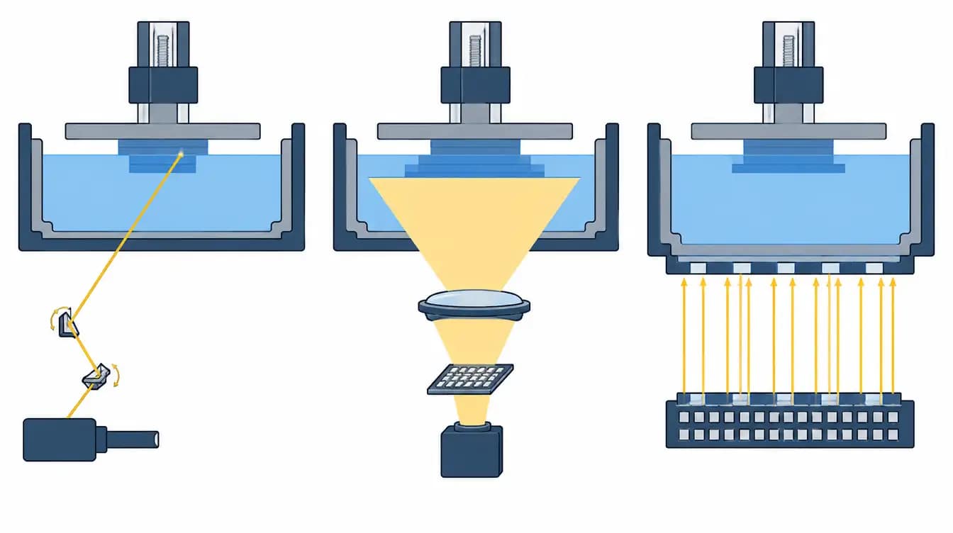
SLA, DLP and LCD are all vat photopolymerization processes. They differ in how light reaches the resin. SLA traces each layer with a laser spot. DLP projects the whole layer from a micromirror chip. LCD, also called MSLA, shines an LED array through an LCD mask. That one difference changes how speed, feature size, build area and running cost scale. It doesn't decide dimensional accuracy, which depends just as much on resin, exposure, orientation and post-processing.
This comparison is written from the process side: how each light engine works, and what that means once parts have to be repeated. It applies to professional and industrial machines. Individual machines differ more than the three categories do, so treat everything below as a guide to what to ask and test, and confirm it on your own part.
How SLA, DLP and LCD expose a layer
All three sit in the category that ISO/ASTM 52900 calls vat photopolymerization: liquid photopolymer in a vat is selectively cured by light. Washing, drying and UV post-curing are broadly the same across them. The light engine is where they part ways.
SLA: a laser draws the layer
A UV laser is steered by two galvanometer mirrors and traces each cross-section, usually the outline first and then the fill. The smallest feature is set by the laser spot and by how precisely the mirrors position it. Because the beam is steered across the scan field, the build area can grow large without the spot getting much coarser, which is why the largest resin machines are laser systems.
DLP: a chip projects the layer
A light source illuminates a digital micromirror device, and projection optics image the whole layer onto the resin at once. The chip has a fixed number of mirrors. Project that image over a small area and the pixels are small; stretch it over a larger area and every pixel grows with it.
LCD (MSLA): a panel masks the layer
An array of UV LEDs sits under a monochrome LCD panel. The panel blocks light where the layer should stay liquid and passes it where the layer should cure. Pixel size is fixed by the panel, and the panel is the same size as the build area, so a larger machine uses a larger panel with more pixels.
One naming caution. Many suppliers use "SLA" for any resin printer, and some LCD machines are sold as "DLP." Before comparing quotations, ask what the light engine actually is.
What the light engine changes in practice
Feature size, and how it scales with build area
This is the least understood difference. On a laser machine, detail follows spot size across the field. On a DLP machine, detail and build area trade against each other, because the same mirrors cover whatever area the optics project. On an LCD machine, pixel pitch stays constant as the platform grows, and the practical limit moves to something else: keeping illumination even across a wide LED array. That's why light uniformity across the build area deserves as much attention as the pixel figure on a large LCD printer.
A small pixel or spot only helps if the resin can hold it. Light scatters and cures slightly beyond the exposed area, and pigmented or filled resins behave differently from clear ones. If the resin's cure spread is wider than the pixel, the extra resolution never reaches the part.
Layer time and throughput
DLP and LCD expose a full layer in one shot, so exposure time is the same for one part or fifty. Laser SLA has to scan every cured area, so layer time rises as the platform fills. A single thin-walled housing scans quickly. A platform packed with solid models doesn't.
Exposure is only part of each layer, though. Lift, peel, resin reflow and settling take time on every machine, and on tall builds that mechanical time often dominates. Quoted millimeters per hour rarely predict the real build time of a specific part.
Surface character
A laser draws outlines as continuous paths, so curves in the XY plane come out smooth. Projection systems build each layer from square pixels, so shallow curves and slight angles in XY can show fine stepping, which anti-aliasing softens but doesn't fully remove. In Z, all three show layer lines set by layer height. On most real parts, orientation and support placement affect the visible surface more than the light engine does.
Resin and wavelength
LCD machines mostly run at 405 nm. DLP light engines are commonly offered at 385 nm or 405 nm. Industrial laser SLA machines often use a shorter UV wavelength, while desktop laser units are usually 405 nm. A resin is formulated for a wavelength and an irradiance level, so it won't necessarily transfer between architectures even when the datasheet looks similar. Ask which resins have validated settings on the exact machine.
Published exposure settings are a starting point at best. A NIST-led interlaboratory study had 24 laboratories measure the cure behavior of the same resin batch and found very large scatter between them, partly because of differences between light engines. Expect to tune exposure on your own machine.
Wear parts and running cost
On an LCD printer the panel itself is a consumable. It has a finite exposure life, and a resin leak through a punctured release film can cure onto it. A failed pixel shows up as a small defect at the same XY position on every layer, which is a quick way to tell a screen problem from a resin problem. DLP light engines generally last far longer but cost more to replace. Laser systems carry the laser's service life and periodic scanner calibration, and large top-down machines hold a big resin inventory in the vat, which makes material changes slow and ties up material cost. A proper maintenance cost estimate should list these items for the specific machine.
| Decision factor | SLA (laser) | DLP (projection) | LCD (masked, MSLA) |
|---|---|---|---|
| How the layer is formed | Laser spot scans the cross-section | Micromirror chip projects the full layer | LED array shines through an LCD mask |
| What limits XY detail | Spot size and scanner positioning | Projected pixel size and lens quality | Panel pixel pitch and light collimation |
| Effect of a larger build area | Spot stays similar; scan time grows | Pixels grow with the projected area | Pixel pitch unchanged; uniformity gets harder |
| Layer exposure time depends on | Total cured area in the layer | Resin and layer height only | Resin and layer height only |
| Common wavelengths | Shorter UV on industrial units; 405 nm on desktop | 385 nm or 405 nm | Mostly 405 nm |
| Main wear items | Laser, scanner calibration, recoater or film | Release film or tank; light engine over the long term | LCD panel, release film |
| Tends to fit | Large one-piece parts, smooth outlines | Small detailed parts, long duty cycles | Full plates of small-to-mid parts, large area at lower equipment cost |
What the technology does not decide: accuracy
Pixel size and spot size describe the light engine. Dimensional accuracy describes the finished part, after shrinkage, support removal, washing and post-curing. The two are related, but one can't be calculated from the other.
YIDIMU's own range shows why the figures aren't comparable. According to the YIDIMU catalogue, the Eternal M2 is an LCD masked-exposure printer with a 46 μm XY pixel size and a 353 × 198 × 400 mm build volume, and the SLA400 is a galvanometer laser SLA system with a typical spot size of 0.1 to 0.2 mm across 400 × 400 × 350 mm. One number is a pixel pitch and the other is a beam diameter. Neither is a tolerance, and neither says which machine holds a given dimension better on a given part.
What usually moves a dimension out of tolerance is less visible: exposure set slightly too high so holes close up, a long flat wall that bows during post-cure, or a part measured before it has fully dried. These happen on all three architectures.
Which process fits which job
Full plates of small, detailed parts, such as dental models, casting patterns or connector housings, favor projection. LCD and DLP expose the whole plate in the time it takes to expose one part.
Large one-piece parts, such as appliance housings, automotive panels or mold masters, favor large-format laser SLA, or a large-format LCD printer when the part fits the panel. The alternative is splitting and bonding, which adds labor and a seam.
Mixed engineering prototypes on a limited equipment budget usually point to LCD, which generally offers the most build area for the investment. A 16-inch class machine such as the Eternal M2 covers most enclosure and fixture work in one piece.
Long production runs with specialty or higher-viscosity resins are where industrial DLP is often chosen, for its light-engine life and irradiance. Laser SLA and LCD can both be the wrong answer here, depending on the resin, and it's worth saying so.
For flexible elastomers, the process window matters more than the light engine. Resin viscosity, peel force and temperature control decide whether a lattice survives the build.
How to compare them with your own part
A demonstration sample shows what a machine can do on a part chosen to flatter it. Your part is the fair test.
Send every supplier the same CAD file, the same resin requirement and the same acceptance criteria.
Ask for the part to be placed at the center and at the corners of the platform, then compare the same feature across positions.
Ask for a full platform as well as a single part. On laser SLA, compare the build times.
Measure after washing, drying and post-curing, and record the measuring method.
Repeat on a second build before drawing conclusions about consistency.
Ask for the wear-parts list and replacement intervals in writing.
Log the whole cycle, including wash, dry and cure, since printer time alone understates it.
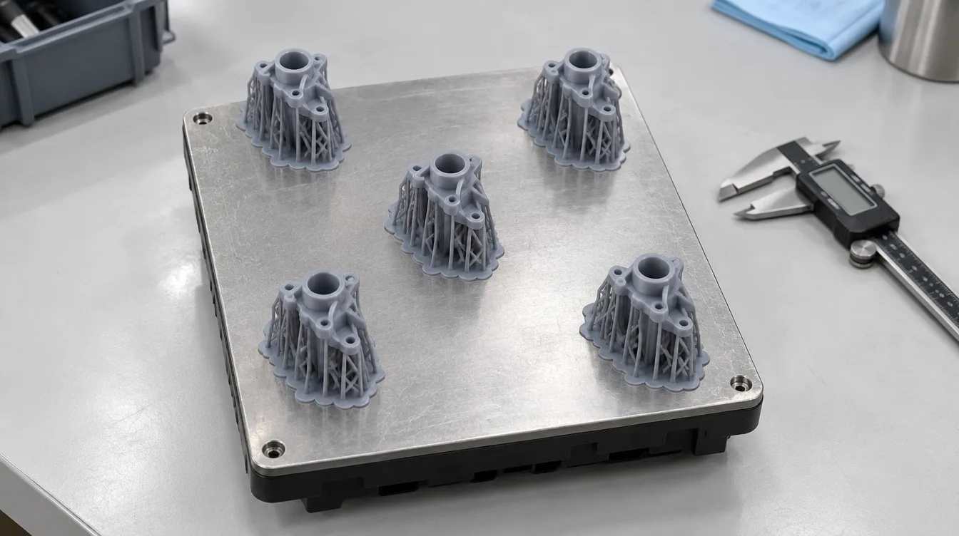
If you'd like to run that comparison on a real part, send the model and your requirements to YIDIMU's application team. Include the material, the critical dimensions and the quantity, and ask for the build layout to be returned with the printed samples.
References
ISO/ASTM 52900:2021, Additive manufacturing — General principles — Fundamentals and vocabulary. https://www.iso.org/standard/74514.html
Kolibaba, T. J., Killgore, J. P., et al. Results of an Interlaboratory Study on the Working Curve in Vat Photopolymerization. Additive Manufacturing, 2024. https://doi.org/10.1016/j.addma.2024.104082
OpenStax, Additive Manufacturing Essentials, Section 2.2: Vat-Based Processes. https://openstax.org/books/additive-manufacturing-essentials/pages/2-2-vat-based-processes
Pagac, M., et al. A Review of Vat Photopolymerization Technology: Materials, Applications, Challenges, and Future Trends of 3D Printing. Polymers, 2021. https://pmc.ncbi.nlm.nih.gov/articles/PMC7922356