
Irradiance distribution
Checks whether optical power is higher or lower at different positions across the build plane.
Resin Printing Fundamentals
Resin 3D printer light uniformity describes how consistently the build plane receives curing light. Poor spatial uniformity can make identical features cure differently at the center, edges and corners. A supplier percentage is useful only when its formula, measurement plane, instrument, grid and operating conditions are defined. The practical test is to combine an irradiance map with repeated printed parts placed across the usable build area.
Direct Answer
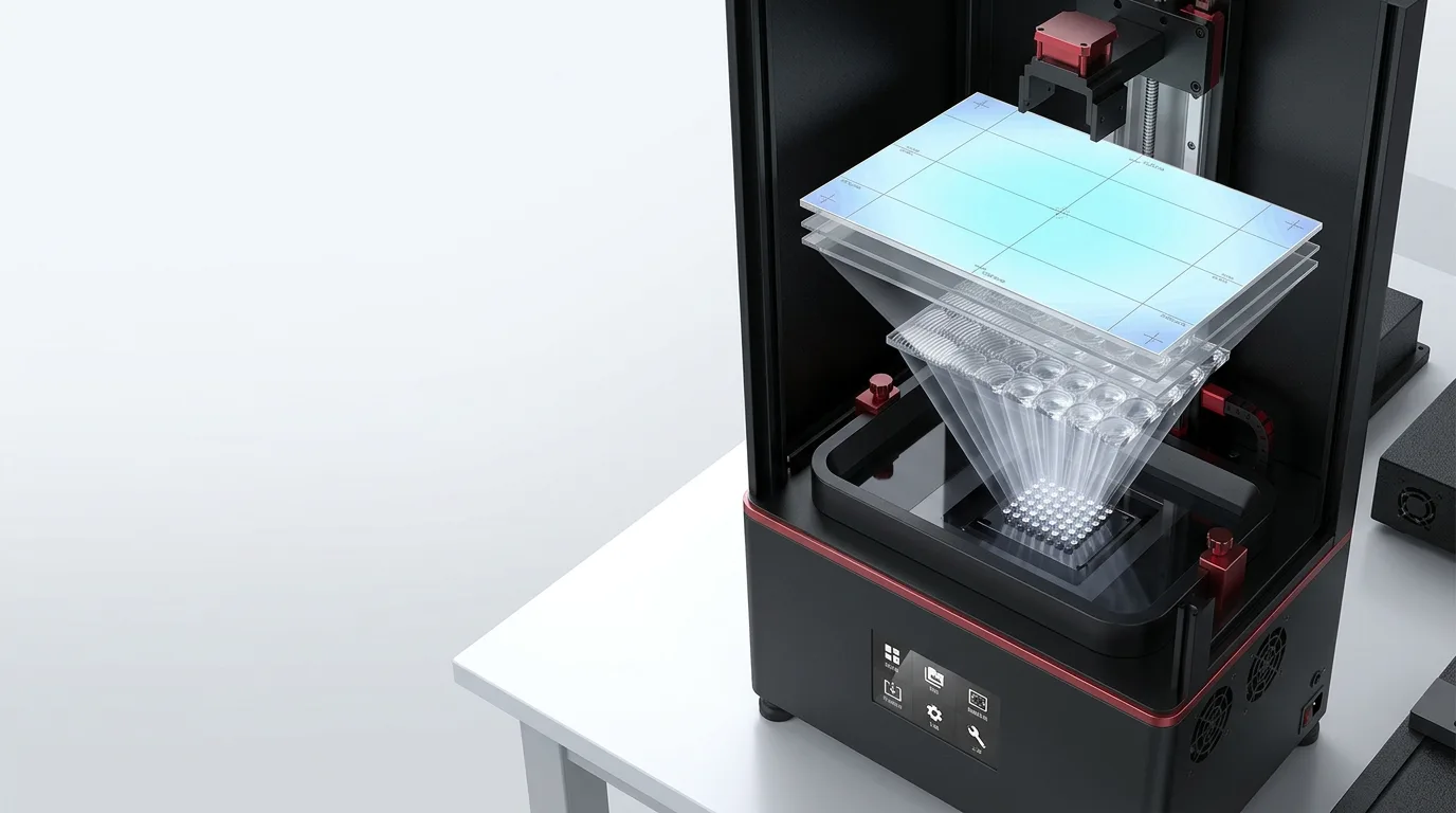
In LCD/MSLA and DLP systems, the optical system exposes a complete layer image. If delivered irradiance, spectrum or ray angle changes by position, the resin may receive a different effective dose even when the same exposure time is used. That can alter cure depth, lateral growth, edge definition, support behavior and surface appearance.
Final results also depend on the resin, layer thickness, temperature, mask or projector behavior, platform alignment, separation mechanics, geometry, orientation, washing, complete drying and UV post-curing. Light uniformity is therefore one process-control variable within a complete vat-photopolymerization workflow.
Definition
Light uniformity is the spatial consistency of curing light delivered over the printer’s intended build plane. In practical terms, it asks whether a feature exposed near the center receives comparable optical conditions to the same feature near an edge or corner.
For LCD or MSLA equipment, an LED-based light engine illuminates a transmissive LCD mask. The mask controls the layer pattern, while lenses, reflectors or other optical components shape the light reaching the resin. For DLP equipment, a projected image passes through projection optics. Laser-based SLA works differently because a focused beam scans the layer rather than exposing the entire layer image at once. The relevant uniformity questions therefore depend on the architecture.
A complete optical assessment can include more than irradiance. Research on LCD-based vat photopolymerization has shown that irradiance, spectral characteristics and optical divergence can vary with position. These variations can change polymerization and part fidelity. A single reading at the center cannot describe this spatial behavior.
Important distinction: irradiance is optical power per unit area at a measurement plane. Radiant exposure is irradiance integrated over exposure time. Resin curing responds to delivered energy and wavelength-dependent photochemistry, so the same time setting does not guarantee the same cure when the optical field changes by location.
Checks whether optical power is higher or lower at different positions across the build plane.
Checks whether wavelength distribution changes by position and how it overlaps the resin’s photoinitiator response.
Checks collimation, focus or ray-angle behavior that can influence pixel edges, lateral cure and feature shape.
Process Impact
Photopolymerization has an exposure threshold and a working relationship between delivered optical energy and cure depth. If one region receives more effective exposure, features there can cure more deeply or grow farther beyond their intended boundaries. If another region receives less, thin features or supports may remain weak or incomplete.
Possible location-dependent symptoms include different hole sizes, thicker or thinner walls, inconsistent text, variable support strength, changes in surface texture, incomplete corner features and different part dimensions across one platform. These symptoms are not proof of a light-engine problem by themselves. Platform parallelism, vat film condition, resin temperature, contamination, separation loads, LCD condition, calibration data and post-processing can produce overlapping effects.
Uniformity becomes particularly important when the build area is used for multiple identical parts. A batch layout assumes that location should not materially change the result. For engineering validation, dental models, jigs, fixtures and repeat production, the acceptance question is not whether every point is mathematically identical. It is whether spatial variation remains within the limits required by the application after the complete workflow.
| Observed pattern | Possible optical contribution | Other factors to check | Useful verification |
|---|---|---|---|
| Parts at one edge are consistently larger | Higher local effective exposure or different ray-angle behavior | Platform tilt, mask scaling, post-cure placement | Measure an irradiance grid and print the same artifact at mirrored positions |
| Corner supports fail more often | Lower local dose may reduce early-layer or support cure | Vat film tension, platform level, resin flow, separation load | Repeat with standardized supports and controlled resin temperature |
| Fine text varies across the platform | Local dose, focus, divergence or mask transmission differences | Slicing compensation, pixel geometry, part orientation | Use identical positive and negative features at several locations |
| One region develops surface texture | Spatial optical heterogeneity may contribute | LCD damage, contamination, release film, wash residue | Inspect the optical path and compare repeated mapped builds |
Specification Review
Manufacturers and instrument vendors may use different calculations for “uniformity.” One method may report the minimum divided by the maximum. Another may compare maximum and minimum values with their average. A third may report deviation from the mean, standard deviation, or a corrected region that excludes border margins. Those values are not directly interchangeable.
Before treating a percentage as a purchasing specification, request the full measurement definition:
A high reported percentage may still hide localized peaks, valleys or repeating patterns between measurement points. A two-dimensional map is more informative than one summary value because it shows where variation occurs.
Validation Workflow
The strongest evaluation combines optical measurement with printed evidence. Optical mapping isolates the light-delivery system; test parts show whether the complete process produces acceptable results. Establish a written procedure before comparing printers so that changes in resin, environment and post-processing do not dominate the result.
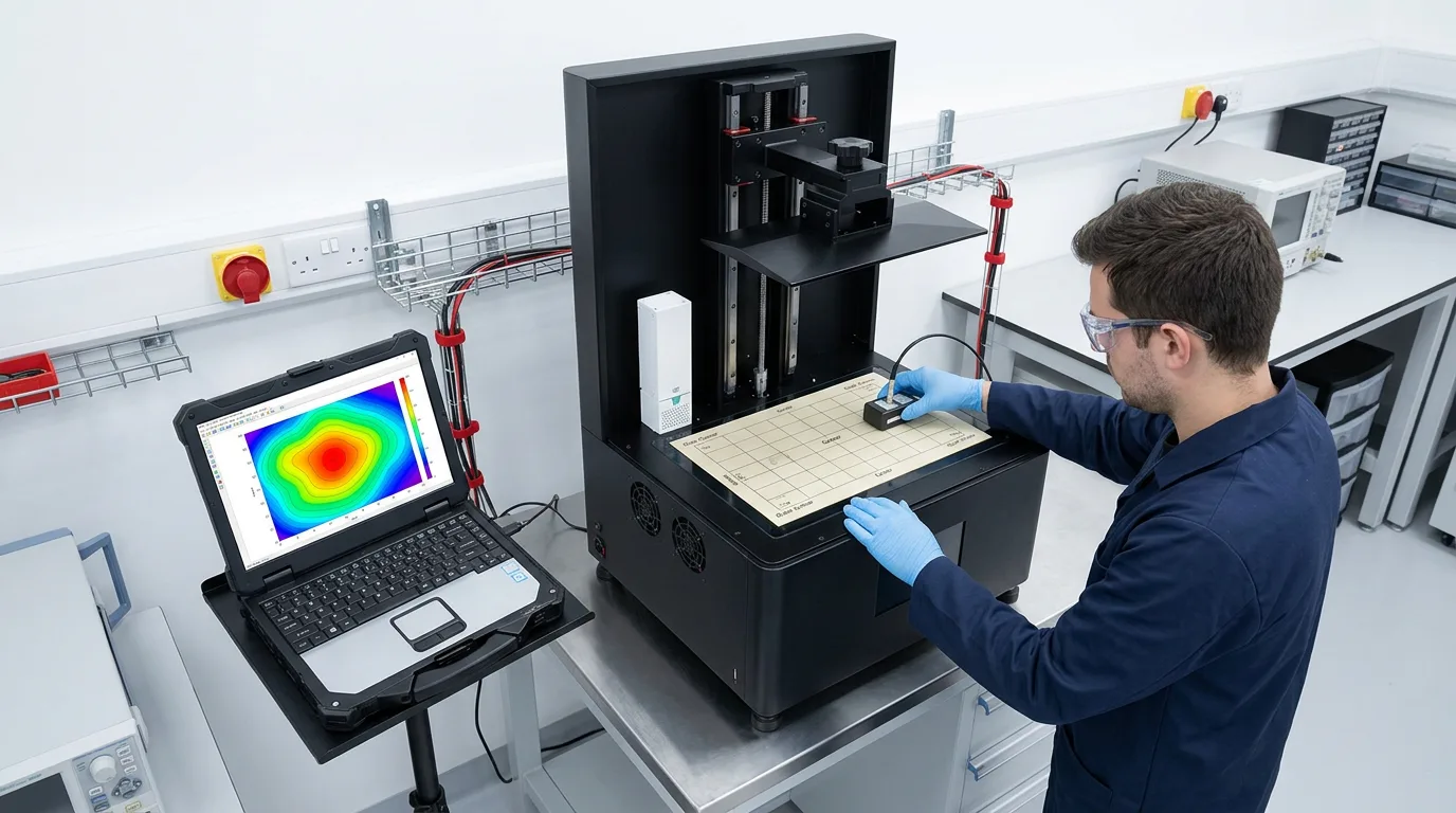
State whether the evaluation covers the full nominal screen, a smaller production region or a specific fixture layout. Connect the test to part requirements such as thin walls, holes, mating features, support reliability or batch consistency.
Record printer configuration, optical compensation, exposure settings, resin batch, resin temperature, room conditions, vat film condition and machine warm-up state. Follow the manufacturer’s safe service procedure before accessing the optical path.
Use a suitable calibrated radiometric detector or validated imaging method at a defined plane. Measure a repeatable grid that includes center, edge and corner positions. Record the raw values as well as the selected uniformity calculation.
Look for smooth gradients, localized low points, LED or lens patterns, asymmetric edges and abrupt discontinuities. Compare the map with service limits or baseline data rather than relying only on the average.
Place identical artifacts at the center, near each edge and in the corners. Include features relevant to the application: positive and negative dimensions, holes, walls, text, supports and flat reference surfaces. Keep orientation and support strategy consistent.
Wash, dry completely, remove supports and UV post-cure with documented conditions. Measure at the same stage for every sample. Uneven washing or curing can otherwise be mistaken for printer light non-uniformity.
Repeat the build to separate persistent spatial behavior from random variation. Save optical maps, print files, settings, maintenance status and measurements. A baseline enables later checks after LCD replacement, optical service or process drift.
UV safety: do not look directly into an operating UV light engine or bypass covers without an approved service procedure and suitable controls. Measurement access should follow the printer and instrument manufacturer’s safety instructions.
Data Interpretation
Begin by separating three questions. First, is there measurable spatial variation in the light field? Second, does that pattern remain stable when the test is repeated? Third, does the complete printing process keep the final parts within application limits?
An optical map and a print map should be compared by location. If higher irradiance regions repeatedly align with larger cured features, deeper cure or stronger overgrowth, the relationship deserves investigation. If optical variation is present but printed results remain within tolerance, the existing compensation and process window may be adequate for that resin and application. If printed variation exists without a matching optical pattern, investigate mechanics, resin condition, platform alignment, separation, thermal behavior and post-processing.

There is no single light-uniformity percentage that guarantees success for every resin, printer or part. A visual prototype may tolerate more variation than an assembly gauge. A dental model workflow may require different validation from a flexible lattice or jewelry pattern. Define the critical features, measurement uncertainty, repeatability target and post-processing stage before deciding whether a result is acceptable.
For formal equipment evaluation, standardized test-artifact concepts can support a structured capability study. ISO/ASTM 52902:2023 describes benchmarking artifacts and measurements for assessing and calibrating additive manufacturing system geometry. It does not replace an application-specific test, but it reinforces the need for defined artifacts, measurements and uncertainty rather than visual judgment alone.
Equipment Evaluation
Light uniformity should be evaluated alongside usable build volume, layer-separation behavior, motion stability, resin compatibility, thermal management, post-processing and technical support. The industrial resin 3D printer buying guide provides a broader equipment-selection framework. You can also review YIDIMU’s industrial resin 3D printer range, photopolymer resin materials and industrial prototyping applications.
FAQ
There is no universal percentage that applies to every machine because calculation methods, measurement grids, detector characteristics and tested areas differ. Compare values only after confirming the formula and procedure, then validate printed parts across the usable build area.
No. It supports consistent exposure, but final accuracy also depends on optical direction, mask or projector behavior, platform alignment, motion, separation, resin chemistry, temperature, geometry, supports and post-processing.
Spatial compensation can reduce some irradiance variation by lowering output in brighter regions. It cannot automatically correct every optical issue, and it may change overall exposure requirements. The corrected system should be remeasured and verified with printed artifacts.
Establish a baseline at installation or process qualification, then recheck according to usage, maintenance policy and application risk. Additional checks are sensible after optical service, LCD or light-engine replacement, unexplained location-dependent failures or meaningful process drift.
A flat sheet may reveal obvious location-dependent curing, but it does not separate optical variation from mechanics, resin flow, platform alignment or post-processing. A better evaluation combines a calibrated optical map with repeated feature artifacts.
Possible causes include spatial exposure differences, optical divergence, platform tilt, vat film condition, mask scaling, resin temperature, separation forces, support behavior and uneven post-curing. Use controlled mirrored placements and repeat builds to isolate the cause.
Application Validation
Share your model dimensions, critical features, resin behavior, quantity, dimensional criteria and post-processing requirements. YIDIMU can discuss equipment options and a representative sample-validation plan without treating a nominal uniformity number as proof of final performance.