Industrial Resin 3D Printing Guide

Large Format Resin 3D Printer for Industrial Parts

A large format resin 3D printer can produce bigger industrial prototypes, housings, tooling and multi-part builds with fewer splits. The right system, however, is not defined by build volume alone. It must control exposure, layer separation, support loads, resin behavior, washing, complete drying, UV post-curing and inspection across the full part.

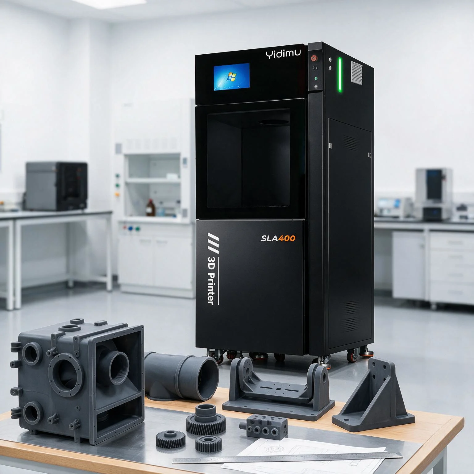
Large industrial resin 3D printer beside engineering housings and fixture parts
Large-format resin printing can reduce unnecessary splits when the oriented part, supports and post-processing workflow are evaluated together.

Direct answer

Choose a large format resin 3D printer for industrial parts when the usable build area reduces unnecessary model splitting or supports an efficient batch layout, and when the complete process can meet the part’s material, dimensional, surface and repeatability requirements.

  • Start with the largest representative part, not the printer specification table.
  • Evaluate usable build volume after orientation, supports, clearance and drainage are included.
  • Confirm resin suitability through current technical documentation and sample testing.
  • Inspect printed parts after the complete wash, dry and UV post-cure workflow.

01 / Define the requirement

What “large format” should mean for an industrial part

There is no single build-volume threshold that makes a resin printer “large format” for every factory. The useful definition is application-based: the printer is large enough when it accommodates the required part or batch with a practical orientation, structurally sound supports, safe edge clearances and a post-processing plan that the team can execute consistently.

A nominal build envelope can be misleading. A housing may fit mathematically but become impractical after it is tilted to protect a cosmetic surface. A tall component may fit in Z but require support towers that increase the effective height. A hollow part may need drain holes and rotation space. A full platform of production aids may create a larger separation load than a single part, even when every model is well within the published dimensions.

Engineering rule:

Compare the oriented and supported file—not only the original CAD bounding box—with the printer’s usable build volume.

When fewer splits are valuable

Printing a larger prototype in one piece can remove bonded seams, alignment features and assembly labor. This is especially useful for appearance models, ergonomic shells, ducts, covers and demonstration parts where a seam can interrupt surface inspection. A single-piece build can also preserve a continuous curve or complex internal passage that would be difficult to align after printing.

Fewer splits do not automatically mean a better process. Dividing a model can reduce support demand, improve orientation of critical surfaces, simplify washing and curing, isolate high-risk features and make replacement easier. The correct decision depends on function, tolerance, finishing requirements and the cost of a failed full-size build.
02 / Compare the complete system

Seven factors to evaluate beyond the build volume

Large-format printing magnifies process weaknesses. A machine should be evaluated as a coordinated system of optics, motion, resin, software, handling and post-processing rather than as a large box with a high-resolution screen.

1

Usable build volume

Check the supported file, edge clearance, platform access, vat capacity and removal method. Ask whether the largest part can be positioned without placing critical surfaces in high-risk areas.

2

Full-area exposure control

For LCD-based vat photopolymerization, uniformity across the light engine matters because spatial variation can affect cure behavior and part fidelity. Nominal screen resolution alone does not prove consistent results across the platform.

3

Layer-separation behavior

Large cross-sections and dense batch layouts increase the demand placed on the release system, motion structure and supports. Evaluate the printer with representative geometry rather than a small calibration model.

4

Material-process match

Resin must be suitable for the intended stiffness, impact, temperature, flexibility, surface and aging requirements. Confirm compatibility and processing conditions in current documentation.

5

Post-processing capacity

The wash container, drying area and UV curing equipment must accommodate the actual part. Oversized components need controlled handling so residual resin, solvent and uncured regions are not hidden in cavities.

6

Inspection and repeatability

Define critical dimensions, cosmetic zones and acceptance criteria before testing. Measure after the complete workflow, because support removal, washing and post-curing can affect the final condition.

7

Service and process support

Ask how profiles are established, how replacement components are supplied, what maintenance is required and what information is needed for technical diagnosis.

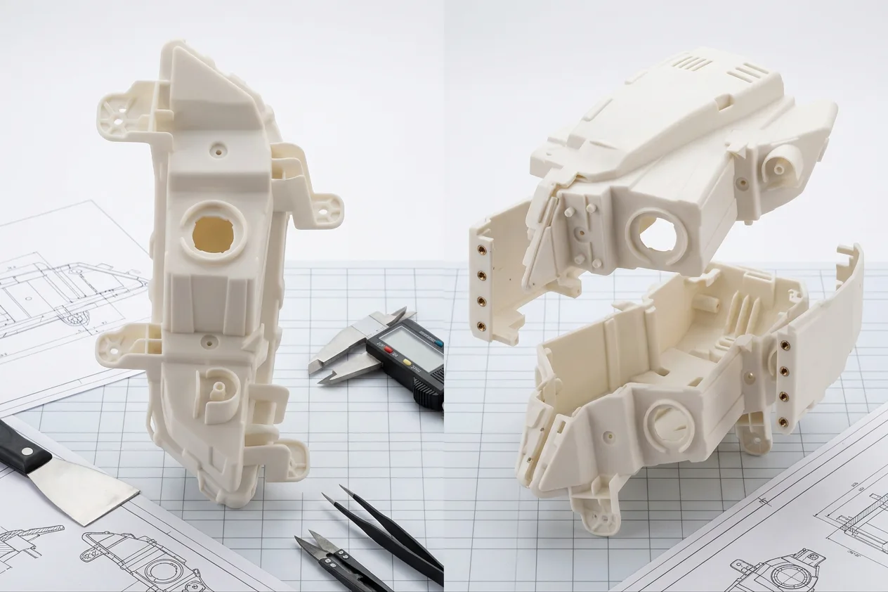
Comparison of a single-piece resin prototype and a split multi-part prototype
A useful comparison shows the same industrial housing as a one-piece build and as engineered sections, including seams, supports and finishing access.

03 / Understand the process

LCD, DLP and laser SLA are not interchangeable terms

All three methods fall within vat photopolymerization, where light selectively cures liquid photopolymer resin. Their light-delivery architectures differ, so buyers should compare actual part performance instead of assuming that one headline specification predicts the result.

TechnologyHow a layer is exposedLarge-format evaluation focus
Laser SLAA directed laser scans the layer geometry.Scan strategy, optical behavior across the working area, recoating or separation control, and the relationship between part location and process time.
DLPA projector exposes a layer image.Projected image quality, optical calibration, usable field size and how resolution changes across the build area.
LCD / masked SLAAn LCD mask controls which areas receive light from the source below or above the vat.Pixel size, light-engine uniformity, optical collimation, mask condition, thermal control and full-platform consistency.

Layer height is a Z-axis slicing choice, while pixel size or projected resolution describes part of the XY exposure system. Neither figure alone proves dimensional accuracy, feature fidelity or repeatability. Those outcomes also depend on resin cure behavior, exposure, geometry, orientation, support strategy, washing, complete drying, UV post-curing, environmental conditions and operator control.

04 / Control the workflow

A practical workflow for large industrial resin parts

The first successful print is not the same as a repeatable manufacturing process. Large parts should move through a documented sequence that connects file preparation to final inspection.

STEP 01

Define acceptance criteria

Record overall dimensions, critical interfaces, cosmetic surfaces, load direction, material expectations and the inspection method.

STEP 02

Prepare the model

Check units, mesh integrity, wall thickness, trapped volumes, hollow sections, drainage and whether splitting improves the process.

STEP 03

Orient and support

Protect priority surfaces, avoid unnecessarily large early layers, support initial load-bearing features and plan safe removal.

STEP 04

Validate the exposure

Use the correct printer-resin profile and confirm it with representative features, not only a generic exposure coupon.

STEP 05

Print and monitor

Confirm resin condition, platform and vat readiness, available volume, environmental range and the planned file version.

STEP 06

Wash and dry fully

Remove uncured surface resin, flush cavities as required and allow solvent or wash fluid to leave the part before curing.

STEP 07

UV post-cure

Follow the current material guidance for wavelength, time, temperature and part positioning. Large geometry may need controlled rotation or staged handling.

STEP 08

Inspect and document

Measure after post-processing, record deviations and surface defects, and update the controlled profile before repeating the build.

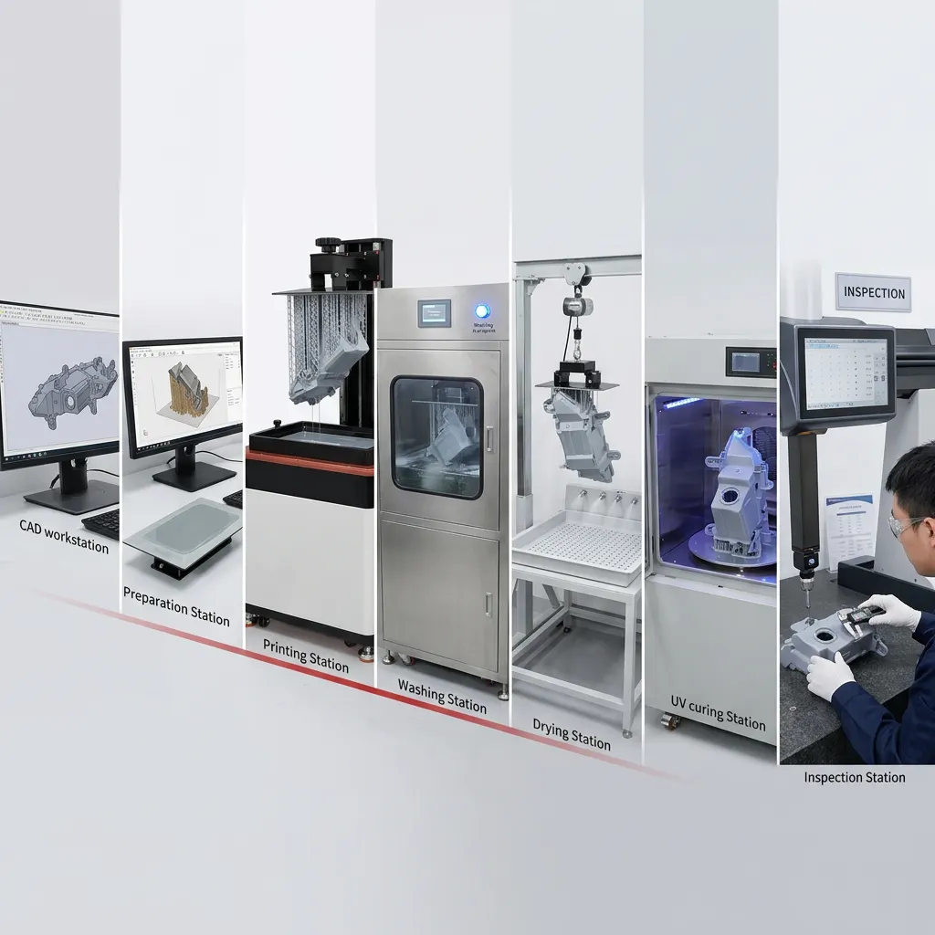
Engineering workflow for preparing, printing, washing, curing and inspecting a large resin part
A controlled workflow connects file preparation, printing, washing, complete drying, UV post-curing and final inspection.

05 / Design for the process

Orientation, supports and hollowing become more important as parts grow

Control the early layers

The first supported regions establish the load path for the rest of the print. Large islands, wide unsupported edges and sudden cross-section changes can overload a support strategy that works on a small model. Review the layer sequence and reinforce the earliest structural features before adding supports to minor details.

Protect the surfaces that matter

Support contact marks, staircase effects and local deformation should be directed away from sealing faces, optical surfaces, inspection datums and visible exterior panels. A slightly longer print can be preferable if it protects the feature that controls acceptance.

Hollow only with a complete fluid path

Hollowing can reduce material use and cross-sectional area, but sealed cavities can trap uncured resin and wash fluid. Drainage, venting, internal access and post-cure exposure must be designed together. Where internal cleaning cannot be confirmed, a solid or split construction may be safer.

Plan removal before printing

A large successful build still needs to be removed from the platform, transferred to washing equipment and supported during curing without damage. Include lifting points, sacrificial tabs or handling fixtures where appropriate.

06 / Match the application

Industrial parts that can benefit from large-format resin printing

Vat photopolymerization is often selected when a project values complex geometry, fine surface reproduction and rapid digital iteration. Final suitability must still be confirmed against the required mechanical, thermal, chemical and environmental conditions.

Appearance and ergonomic prototypes

Full-size covers, control panels, handheld enclosures and presentation models can be inspected without multiple visible seams. Finishing requirements should be included in the build orientation.

Assembly and fit-check models

Housings, brackets, ducts and interface parts can reveal clashes, cable-routing problems and access issues before tooling. Critical features should be measured after post-curing.

Jigs, fixtures and production aids

Positioning tools, drill guides, nests and inspection aids can be printed when the selected resin and geometry match the applied load, temperature, wear and chemical exposure.

Master patterns and process models

Large patterns can support molding, casting preparation or visual review. The downstream process may require controlled shrinkage allowance, surface finishing and venting features.

Small-batch components

A large platform can arrange multiple parts in one build, but production readiness depends on repeatable placement, inspection, traceability, resin management and post-processing capacity.

Research and custom equipment parts

Laboratories and engineering teams can create complex channels, covers, mounts and test geometries quickly, provided the material limitations are compatible with the experiment.

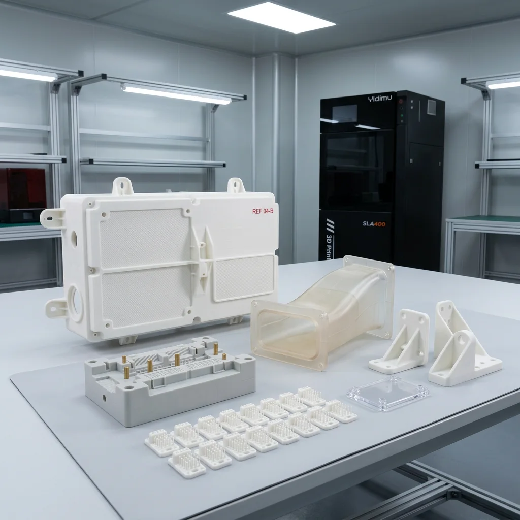
Industrial resin 3D printed housings, fixtures and batch parts on an engineering workbench
Typical industrial output includes large housings, inspection fixtures, ducts, mounting brackets and controlled batches of repeated parts.

07 / Calculate total workflow capacity

Throughput is not the same as advertised print speed

For a large format resin 3D printer for industrial parts, useful throughput is the number of accepted parts delivered per period—not the maximum vertical speed shown on a specification sheet.

Capacity questionWhat to measureWhy it matters
How long is the complete cycle?Preparation, print, draining, wash, drying, cure, support removal, finishing and inspection.A fast exposure process can still be limited by manual handling or post-processing queues.
How many accepted parts fit?Supported layout, spacing, resin volume, separation load and inspection yield.Nominal platform area does not equal saleable or usable output.
What happens after a failed build?Resin filtering, vat inspection, film or release-surface checks, platform cleaning and rescheduling.Recovery time changes real availability and operating cost.
How stable is the controlled process?Part-to-part deviation, location effects, repeat builds and profile revision records.Repeatability determines whether the system supports production rather than occasional prototyping.
What is the total material burden?Part resin, supports, trapped resin risk, wash fluid, consumables and rejected parts.Part cost depends on the full workflow, not only model volume.

Before purchasing, run a representative build that includes the largest geometry, the smallest critical feature, a difficult cosmetic surface and the intended batch density. That test reveals more about practical capacity than a demonstration part selected only for visual impact.

08 / Validate before selection

Use representative sample testing to reduce equipment-selection risk

A supplier evaluation should connect your CAD file, resin requirement, workflow and acceptance criteria. The goal is not to prove that the printer can produce any object; it is to determine whether the proposed system can produce your part under a documented process.

Information to provide

  • Original CAD or a watertight export with confirmed units.
  • Overall dimensions and quantity per build or per month.
  • Critical dimensions, fits, datums and cosmetic surfaces.
  • Required stiffness, flexibility, impact, temperature or chemical behavior.
  • Expected downstream finishing, assembly and service environment.
  • Inspection method and acceptable deviation.

Evidence to request

  • The supported orientation and explanation for critical decisions.
  • The printer, resin and profile used for the sample.
  • The complete wash, drying and post-cure procedure.
  • Measurements taken after final post-processing.
  • Known limitations, sensitive features and recommended design changes.
  • Current specifications, material documents and maintenance requirements.

09 / Common questions

FAQ about large-format resin printing for industrial parts

Can a large resin part be printed without splitting?

Yes, when the oriented and supported model fits within the usable build volume and the workflow can manage separation loads, drainage, removal, washing, drying and post-curing. Splitting may still be preferable when it improves surface quality, access, risk control or serviceability.

Does a larger LCD resolution guarantee better accuracy?

No. Resolution and pixel size describe parts of the imaging system, but final accuracy also depends on light uniformity, optical behavior, resin cure response, exposure settings, geometry, orientation, supports and post-processing. Confirm performance with measured representative samples.

What resin is best for industrial parts?

There is no universal best resin. Select the material from the required stiffness, toughness, flexibility, temperature, chemical exposure, surface and aging conditions. Verify the current technical data and test the actual part under representative conditions.

How should large hollow parts be cleaned and cured?

Design accessible drain and vent paths, remove uncured resin, flush the cavity according to the material workflow, allow complete drying and ensure UV exposure can reach the required surfaces. Avoid sealed cavities that cannot be inspected or processed reliably.

What should be included in a supplier sample test?

Use the largest representative geometry, critical dimensions, important surfaces, difficult overhangs and intended batch density. Request the orientation, support strategy, printer-resin profile, post-processing procedure and measurements after final cure.

Can large-format resin printing support small-batch production?

It can, when the printer, resin, layout, post-processing and inspection process produce repeatable accepted parts. Evaluate complete cycle time, failure recovery, consumables, traceability and operator workload rather than relying only on nominal print speed.

Evaluate the real part

Compare printer, resin and post-processing options around your model

Share the part dimensions, material requirements, quantity, critical features and target workflow. YIDIMU can review the model for build-volume fit, orientation, sample printing and equipment selection.

Discuss Your Application