
Flexible Resin Dimensional Accuracy: Causes & Control
When a flexible resin part comes out of the workflow the wrong size, the printer is rarely the only suspect. A soft photopolymer keeps changing shape long after the light source has drawn the layer: it stretches during peel, sags on its supports, absorbs solvent in the wash, shrinks in post-cure and compresses under the jaws of whatever tool is used to check it. Flexible resin dimensional accuracy is therefore a property of the whole process and the measurement method, not a number that can be read off a printer specification.
Flexible resin parts are usually harder to hold to size than rigid resin parts printed on the same machine. The extra error comes from cure spread at longer exposures, deformation of the soft green part during printing, solvent swelling during washing, shrinkage and stiffening during post-curing, and measurement force. Achievable tolerance depends on the resin, Shore hardness, wall thickness, geometry, process settings and how the part is held when it is measured. It has to be established with representative parts run through the complete, fixed workflow.
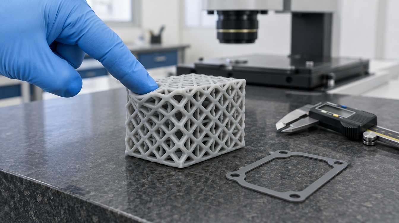
A soft part has more ways to move than a rigid one
With a rigid resin, most dimensional error is set while the part is being built: how far the cure spreads beyond the exposed area, how the part shrinks as it polymerizes, and whether it warps as it is post-cured. Once cured, the part largely stays where it is, and a caliper or micrometer reads it without changing it.
An elastomer removes that stability at almost every stage. The partially cured part is compliant enough to be pulled out of position by the forces of normal printing. The cured network can take up solvent and swell. And because the finished material is designed to deform under small loads, the act of measuring becomes a source of error in its own right. None of this means flexible parts cannot be dimensionally reliable, but the error budget is wider and has more contributors, so it must be managed stage by stage.
Where the dimensional error enters the workflow
The table below maps each stage to the mechanism that moves the dimension, what that usually looks like on the part, and the lever that controls it.
| Stage | What moves the dimension | What you typically see | Main control lever |
|---|---|---|---|
| Exposure | Cure spreads past the edge of the exposed area; flexible resins are often run with longer exposure so the soft green part survives peel | Outer walls slightly oversize, holes and lattice cells undersize or closed, struts thicker than modeled | Exposure calibration in the production resin; feature-level CAD offsets |
| Layer separation (peel) | The partially cured part stretches and recovers with every layer as it releases from the film | Wavy thin walls, displaced or bent struts, small Z growth, layer misregistration | Orientation that reduces large cross-sections; lift settings; support density |
| Supports and gravity | Soft regions hang from the platform and deflect under their own weight and the resin's drag | Drooping overhangs, flattened curves, dents at support contacts | Orientation; supports on non-functional faces; avoiding long unsupported spans |
| Resin temperature | Viscosity and reactivity change with temperature, which changes recoating and effective cure | Builds that measure differently on different days or shifts | Controlled resin or chamber temperature; consistent warm-up |
| Washing | The elastomer network absorbs solvent and swells; residual resin is left in fine features if the wash is too short | Temporary oversize and soft, tacky surfaces; dimensions that drift for hours afterward | Short, fixed wash time; complete evaporation before curing |
| Post-curing | Further crosslinking adds shrinkage and changes hardness; uneven exposure in the curing unit adds distortion | Slight overall shrinkage, curl on thin sections, stiffer-than-expected parts | Fixed time, temperature and part placement in the curing unit |
| Measurement | Contact force compresses the part; the reading depends on how the part is supported | Different results from different operators or tools on the same part | Non-contact or defined low-force methods; defined holding condition and rest time |
Exposure: why holes close and struts grow
On an LCD masked-exposure printer, the screen defines which pixels transmit light, but resin does not stop curing exactly at the pixel boundary. Scattering and diffusion widen the cured region, and the effect grows with exposure energy. Flexible resins are frequently run with longer exposure than rigid resins, partly to give the green part enough strength to survive repeated peel. The result is a systematic bias: positive features grow, negative features shrink, and in lattices the cell openings tighten. A smaller XY pixel size gives a finer grid to draw on, but it does not remove this spread, which is why pixel size and dimensional accuracy have to be treated as separate questions.
Peel and viscosity: the soft green part as a spring
Every layer is pulled away from the release film. A rigid green part transmits that force to the platform with little deflection; a soft one stretches first. Large cross-sections increase the separation force, and thin, tall features are where the deflection shows up. Resin viscosity compounds the problem. YIDIMU's elastomeric resin, for example, is listed at 2,500–3,000 cps at 25 °C, while its rigid resin is listed at 150–200 cps under the same condition. A thicker resin flows back more slowly between layers and drags harder on fine features, and because viscosity falls as temperature rises, a cold machine and a warm machine will not behave the same way with identical settings.
Washing and curing: the dimensions keep moving after the print
Elastomers absorb solvent more readily than densely crosslinked rigid resins. A long soak, or a thin, high-surface-area part such as a gasket or lattice, can come out of the wash measurably oversized and soft. If that part goes into the curing unit before the solvent has evaporated, some of the swelling can be locked in. Post-curing then continues the polymerization, which brings additional shrinkage and usually a change in hardness. The order matters: changing wash time or drying time can shift the final dimension even when every printer setting stays the same. For a broader view of how washing and curing change flexible materials, see this engineer's guide to flexible resin 3D printing.
Measuring a part that changes shape when you touch it
A caliper that reads a rigid part reliably can produce a dimension on a 50A elastomer that depends largely on how hard the operator squeezes. Laboratories that inspect elastomer components often favor non-contact methods for exactly this reason. For printed flexible parts, a useful measurement plan defines four things before any number is recorded:
Method. Optical measurement, 3D scanning or a vision system for outlines and lattice features; contact tools only with a defined, low measuring force, and only where the material and geometry allow it.
Holding condition. Free state on a flat reference surface, or constrained in a fixture that reproduces the installed condition. A seal or insole may only have a meaningful shape once it is in its mating part, and a go/no-go assembly check can be more relevant than a free-state dimension.
Timing and environment. A fixed rest period after post-curing and a consistent room temperature, so that solvent evaporation and thermal effects are not mistaken for process variation.
Datums. Which features define the coordinate system. On a soft part, choosing a datum on a feature that deflects easily will move every other reading with it.
It also helps to check the tolerances on the drawing itself. Drawings for flexible parts are sometimes copied from rigid-part templates and carry limits that were never intended for a soft material. Molded rubber, for comparison, has its own dimensional tolerance classes in ISO 3302-1, graded by how critical the dimension is. Printed elastomer parts are not the same as molded rubber, but the principle carries over: tolerance should reflect the function of the dimension and the material, not a general block tolerance from a machined-part template.
Decide which dimensions actually matter
Not every feature on a flexible part deserves the same attention. A useful split is between dimensions that control fit or sealing, dimensions that control mechanical response, and dimensions that are cosmetic.
Fit and sealing features, such as a lip, a groove or a snap interface, usually need the tightest control and the most careful measurement plan. Mechanical-response features behave differently. In a lattice midsole or cushioning pad, strut thickness and cell size directly change compression stiffness, so a lattice whose struts all print slightly oversize can still meet its outline tolerance yet feel noticeably firmer. For these parts, a compression test or a part-mass check is often a better indicator of dimensional consistency than an outline measurement. Hardness interacts with geometry here as well; choosing Shore A hardness for 3D printed flexible parts covers that side of the problem.
Bringing flexible parts to size: a practical sequence
Compensation only works on a stable process. Scaling a model to correct an error that changes from build to build simply moves the error around. A workable order is:
Fix the inputs. One resin lot or a qualified lot range, a defined resin and room temperature, fixed layer height and exposure settings.
Calibrate exposure in the production resin. Print a test coupon containing holes, pins, thin walls and a small section of the real lattice. Tune exposure until features resolve cleanly without excessive growth, then record the remaining bias.
Set orientation and supports for the soft geometry. Place supports on non-functional faces, reduce large single-layer cross-sections where possible, and avoid long unsupported spans that will sag.
Standardize washing and drying. Fix the wash time, agitation and solvent condition, and set a minimum drying time before curing.
Standardize post-curing. Fix time, temperature and the position of parts in the curing unit.
Measure with the defined plan. Same method, holding condition and rest period every time.
Compensate, then confirm. Apply feature-level offsets for holes, slots and struts first; use per-axis scaling only for the systematic bias that remains. Re-run the full workflow and measure again.
Check repeatability. Print the same part across several builds and several platform positions. A process that hits nominal once but scatters across builds is not ready for production.
Any change to resin, exposure, wash or cure settings invalidates the compensation values and should trigger a re-check. The same applies after maintenance that affects the optical path or release film.
What the printer specification can and cannot tell you
Printer data sheets describe the machine: build volume, XY pixel size, layer height range, and sometimes a stated print accuracy measured under the manufacturer's own conditions. They describe capability, not the tolerance of a specific flexible part. Layer height sets the Z step, not Z-axis accuracy. XY pixel size sets the exposure grid, not the finished outline. For flexible work, the more useful questions are whether the machine holds resin temperature steadily, how it handles release forces with soft parts, and whether its results repeat from build to build. The distinction between hitting a target and hitting it consistently is covered in 3D printing accuracy vs precision.
Equipment considerations for elastomer work
Because so much of the error comes from viscosity, release behavior and temperature, elastomer printing benefits from equipment set up specifically for soft materials rather than rigid-resin machines adapted after the fact. Flex G2 is a 14-inch 16K LCD masked-exposure printer dedicated to elastomer resins, with a 302 × 162 × 370 mm build volume and a compatible hardness range of 50A–90A; it suits lattice structures, insoles and other flexible development parts at benchtop scale. For larger flexible parts such as full midsoles or protective pads, the floor-standing Extreme 450 Pro offers a 450 × 253 mm platform with configurable build height and automatic chamber temperature control, which directly addresses the temperature sensitivity described above.
Neither machine removes the need for process qualification. Dimensional results on a flexible part still depend on the resin, the geometry, the wash and cure routine and the measurement plan, which is why representative test parts are the right basis for any tolerance commitment.
Before committing to a tolerance on a flexible part
Which dimensions are functional (fit, sealing, stiffness), and which are cosmetic?
Is each tolerance realistic for the material's hardness and the feature's wall thickness?
Is the measurement method defined, including holding condition, contact force and rest time after curing?
Have exposure, wash, drying and post-cure settings been fixed before compensation is applied?
Are lattice dimensions also checked through a functional proxy such as compression response or part mass?
Has the part been printed across several builds and platform positions to confirm repeatability?
Will any change in resin lot or process settings trigger re-verification?
Common questions
Why are my flexible resin prints oversized?
The usual causes are cure spread from long exposure, solvent swelling after a long wash, and parts that were cured before the solvent evaporated. Check whether the oversize is uniform or concentrated on thin, high-surface-area features; swelling tends to affect thin sections most.
Should I scale the CAD model to compensate?
Only after the process is stable and the measurement method is fixed. Start with feature-level offsets for holes and struts, then apply per-axis scaling for any remaining systematic bias, and re-verify whenever resin or settings change.
Can calipers be used on flexible parts?
For harder elastomers and robust features, carefully, with a consistent light force. For soft materials, thin walls and lattices, optical or scanning methods, or a functional fixture check, give more repeatable results.
Test your own flexible part before setting the tolerance.
Send YIDIMU a representative CAD file with the target hardness, the critical dimensions and how you plan to measure them. Our team can help assess the geometry, the material and process route, and which elastomer system fits the part, so the tolerance discussion starts from real printed samples rather than assumptions.