
Direct Answer
What Shore A hardness should a 3D printed flexible part use?
The correct Shore A hardness for 3D printed flexible parts is the value that meets a defined use requirement after the part has been printed, washed, completely dried and UV post-cured according to the resin’s approved technical instructions. Lower Shore A values generally indicate easier indentation; higher values indicate greater resistance to indentation. That does not mean a lower number automatically gives better cushioning or a higher number gives better rebound. Wall thickness, lattice topology, loading direction, resin chemistry, curing history and temperature all influence the finished response. Select an initial material range from documented data, then test a standard specimen and a representative part under the real load, fit and environmental conditions.
Key Takeaways
Six points that prevent the wrong material decision
Understand the Measurement
What Shore A hardness does—and does not—tell you
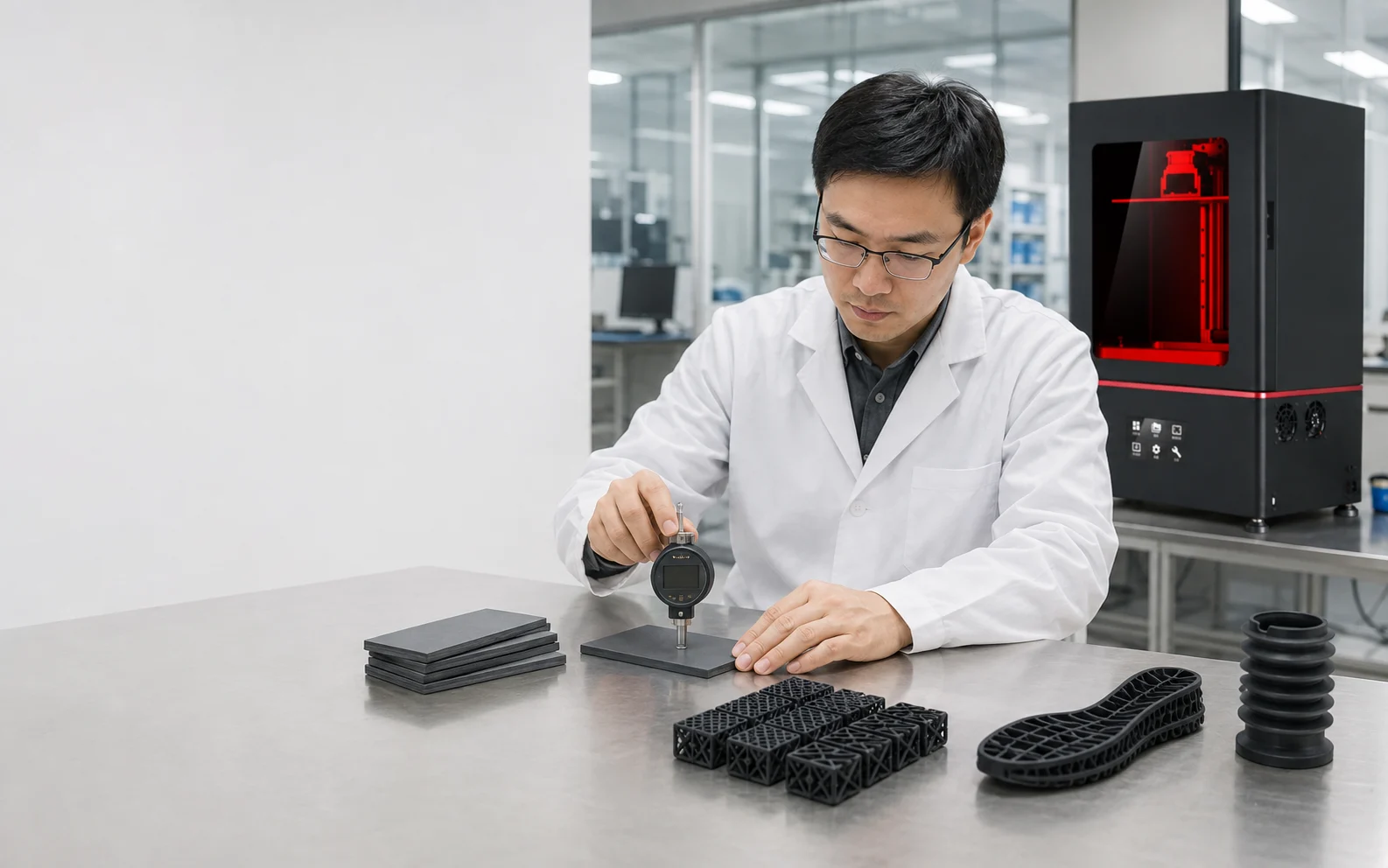
A Shore durometer presses a defined indenter into a material under specified conditions. The reading reflects resistance to that penetration. ASTM D2240 and ISO 48-4 describe recognized durometer methods, including the Shore A scale for rubber in a normal hardness range. The chosen standard, edition and laboratory procedure should be stated in the validation plan.
The result depends on more than the resin name. Specimen thickness, support from the surface beneath it, distance from an edge, contact force, reading time, temperature and material conditioning can all change the reading. A value taken casually from a thin lattice strut or curved shoe part is not equivalent to a standardized material result.
Useful for comparing properly prepared elastomer specimens under one method.
Review tensile, elongation, tear, rebound and compression behavior as required.
Test fit, deflection, cushioning, sealing or movement in the intended geometry.
Selection Framework
How to select Shore A hardness for 3D printed flexible parts
Begin with the function, not a familiar rubber comparison. Write down how the part is loaded, how far it may deflect, whether it must recover quickly, what it contacts and which failure mode matters. Then use documented resin data to define a short list. YIDIMU currently presents a 50A–90A elastomer material-hardness window for its Flex G2 and Flex Pro flexible printing systems; the exact resin, printer profile and finished result still require confirmation.
| Initial band | When to investigate it | Geometry questions | Required validation |
|---|---|---|---|
| Approximately 50A–60A | When easy deformation, soft contact or a highly compliant response is important. | Will thin walls, small lattice members or supports survive printing, cleaning and handling? | Tear resistance, recovery, surface condition, minimum feature robustness and repeated compression. |
| Approximately 60A–75A | When the design needs a balance between compliance and structural support. | Can wall thickness or lattice density tune local stiffness without changing resin? | Load–deflection curve, rebound, fit, interface pressure and cyclic behavior. |
| Approximately 75A–90A | When greater indentation resistance, shape retention or a firmer flexible response is required. | Will the finished part still bend at hinges, bellows or contact zones without stress concentration? | Flex fatigue, tear initiation, assembly force, compression set and environmental exposure. |
Translate the use case into measurable requirements
- Footwear and cushioning: define force–displacement behavior, energy return, bottoming-out, local pressure and cyclic durability rather than hardness alone.
- Gaskets and seals: define compression, contact pressure, allowable compression set, fluid or chemical exposure and sealing leakage criteria.
- Bellows and soft-robotic elements: define motion range, actuation force, fold location, fatigue cycles and tear-sensitive transitions.
- Wearables and protective components: define skin-contact status, fit, edge comfort, cleanability, impact or damping test and applicable regulatory requirements.
Design Variables
Material hardness is not component stiffness
Two parts printed from the same resin can feel very different. Increasing a solid wall thickness, shortening a flexible span or increasing lattice relative density can make the component harder to deform even though the material’s measured Shore A hardness is unchanged. The reverse is also true: slender ribs, longer hinges, larger cells or thinner skins can create a more compliant component from a firmer material.
This distinction matters when a team tries to “fix” a stiff part by changing resin before reviewing CAD. Material and geometry should be treated as two independent design levers. A useful evaluation matrix prints several geometries in one controlled material and, separately, the same geometry in two or more candidate materials.
Design details that deserve early review
- Minimum wall and strut dimensions that can be printed, washed and handled without damage.
- Gradual transitions between flexible and rigid regions to reduce tear initiation.
- Drainage and cleaning access in hollow structures and internal lattices.
- Support locations away from sealing faces, contact zones and hardness-test surfaces.
- Build orientation relative to expected bending, tension and layer interfaces.
- Space for swelling, compression and deformation during assembly or use.
Controlled Workflow
Print, wash, completely dry and post-cure before comparison
Flexible photopolymers should be compared in the finished state that will actually be tested or used. Residual resin or cleaning fluid can distort surface feel and measurement. UV post-curing can change conversion and mechanical response, while excessive or incorrect processing may also change performance. Never transfer generic wash or cure times between materials. Follow the exact resin TDS, SDS, IFU and approved printer profile.
Lock the material and process revision
Record resin name, batch, printer, profile, layer setting, build orientation and support strategy. A change to any controlled input creates a new comparison condition.
Print representative coupons and parts together
Use a suitable standardized specimen for hardness comparison and include the real component or a representative section for functional testing.
Wash according to formal material instructions
Use the specified cleaning medium and handling method. Avoid leaving uncured resin in cavities or lattice intersections, and use the required personal protective equipment.
Allow complete drying
Do not post-cure or measure a specimen that still contains surface or trapped cleaning liquid. Complex lattices and enclosed channels need particular attention.
UV post-cure under the approved conditions
Control wavelength, irradiance, time, temperature, part placement and rotation as required by the resin documentation. Keep the sequence identical across candidates.
Condition, inspect and test
Use the specified conditioning period and test environment. Check for tack, residue, cracks, support damage and distortion before recording hardness or functional results.
YIDIMU lists UV curing and supporting equipment as part of the broader post-processing workflow. Equipment selection does not establish a universal cure cycle; the resin documentation controls the actual process.
Measurement Plan
How to verify Shore A without producing misleading data
A defensible result needs a written method. Select ASTM D2240, ISO 48-4 or another applicable requirement and use the current edition relevant to the project. Prepare a specimen with the required thickness, flatness and dimensions; do not improvise those values from a thin production part. Use a calibrated Shore A durometer and a controlled support surface. Where repeatability matters, a stand helps control contact and alignment.
Define the reading time, test temperature, conditioning, number and location of measurements, distance from edges and how results will be reported. Keep indents separated according to the chosen method. Record individual readings as well as the average and spread; a single central reading can hide spatial variation or a damaged area.
Why direct readings on lattices are usually inadequate
A durometer foot needs a suitable test surface and underlying material. On an open lattice, curved wall, narrow rib or thin skin, the structure deflects and the substrate may influence the reading. That value can still be useful as an internal process indicator if the fixture and method are fixed, but it should not be presented as a standard material Shore A result. Use a qualified coupon for material hardness and a load–deflection or compression test for the lattice.
Relevant YIDIMU Systems
Flexible printing systems to evaluate around the part
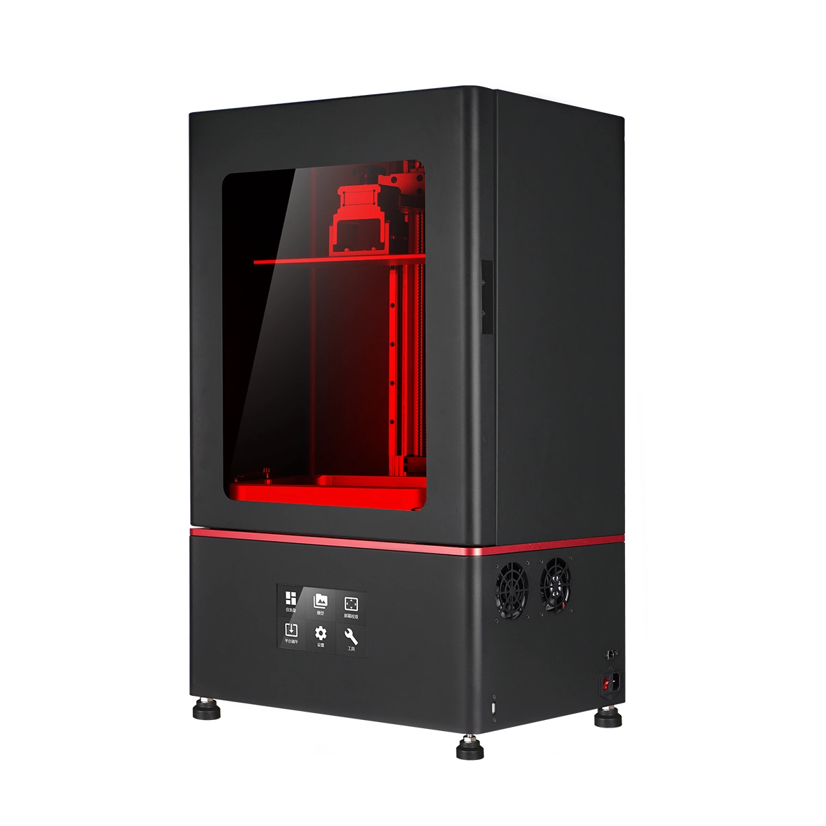
YIDIMU’s current public product information identifies Flex G2 and Flex Pro for flexible lattices, cushioning structures, footwear development, soft robotics and other elastomer components. Both pages list a 50A–90A flexible-material hardness range. Final suitability depends on the selected resin, build envelope, geometry, profile, post-processing and representative sample results.
Flex G2
YIDIMU positions Flex G2 for flexible lattices, cushioning structures, footwear and elastomer part evaluation. Check the current product page for the approved configuration and technical data.
View Flex G2 product information →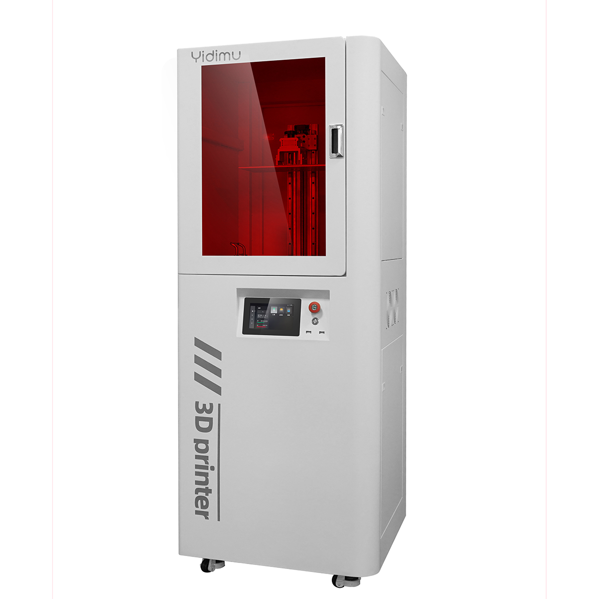
Flex Pro
YIDIMU positions Flex Pro for larger flexible elastomer parts and multi-part layouts. Confirm build requirements, resin matching and final configuration for the specific project.
View Flex Pro product information →Review the complete YIDIMU flexible and elastomer printer range and available photopolymer resin materials before choosing a test configuration.
Practical Evaluation Checklist
Information to prepare before sample testing or quotation
Limitations and Validation
A datasheet cannot qualify the finished part
Published hardness helps narrow the material search, but it cannot establish performance for an untested design. Printed photopolymers can respond to part orientation, exposure, feature size, supports, washing, complete drying, UV dose, temperature, measurement timing and aging. A representative test should preserve the geometry, resin, printer profile and complete post-processing route expected in production.
Use at least two levels of evidence: standardized coupons for material comparison and representative parts for fit and function. If the application is safety-related, regulated, load-bearing or exposed to repeated deformation, chemicals, outdoor weathering or elevated temperature, define the applicable engineering and regulatory tests with a qualified specialist. Do not infer biocompatibility or dental suitability from softness, color or a generic “flexible resin” label.
The resin 3D print quality inspection checklist can help structure finished-part review after post-processing. For footwear and lattices, the flexible structures and footwear application page provides a part-first evaluation path.
Frequently Asked Questions
Shore A hardness for flexible resin printing FAQ
Is 80A twice as hard as 40A?
No. Shore A is an empirical indentation scale, not a linear ratio scale. Use measured specimens and functional tests rather than treating numerical differences as proportional changes.
Does a higher Shore A value mean better rebound?
No. Hardness and rebound describe different behavior. Resin chemistry, viscoelastic response, geometry and temperature can produce different rebound at a similar hardness.
Can I measure Shore A directly on a printed lattice?
A lattice reading is usually not a standard material-hardness measurement because the structure deflects beneath the indenter. Test a compliant standard coupon for material comparison and use compression or load–deflection testing for the lattice.
Does UV post-curing change Shore A hardness?
It can change mechanical response because post-curing changes the photopolymer network. The direction and magnitude are resin- and process-specific, so follow the approved cure instructions and measure only after the controlled final process.
Is Shore A enough to select resin for a gasket?
No. Also validate sealing pressure, compression set, tear resistance, surface quality, mating geometry, chemical exposure, temperature and service duration.
Does YIDIMU’s 50A–90A range guarantee every finished part value?
No. It is the currently listed material-hardness window for the flexible systems. Confirm the exact resin documentation, printer compatibility, workflow and representative finished-part result for the project.
Related Resources
Continue the technical evaluation
Project Evaluation
Submit the part—not only a target hardness number
Provide the model file, overall dimensions, intended use, target material behavior, quantity, critical surfaces, mating requirements, tolerances, post-processing expectations and inspection method. YIDIMU can review a suitable printer, resin and representative sample-evaluation route without treating the datasheet as a substitute for part validation.
Submit Your Model and Requirements →