
Direct Answer
How should industrial resin 3D printer accuracy be verified?
Industrial resin 3D printer accuracy verification should compare measured, fully processed parts with controlled nominal geometry under a written test plan. Use both a benchmark artifact and a representative project part; place repeated features at relevant build-area positions; keep the printer, resin, file, orientation, supports and post-processing conditions traceable; and measure only after the agreed washing, complete drying, UV post-curing and finishing sequence. Judge systematic dimensional bias, variation between repeated parts and builds, location-dependent behavior, feature integrity and functional fit separately. Pixel size, layer thickness and one successful sample do not establish finished-part accuracy or production repeatability.
Key Takeaways
Five rules that keep an accuracy test meaningful
Define the nominal model, critical dimensions, datums, fit relationships and allowable deviation before the build.
XY pixel size and layer thickness describe sampling or process settings, not the final tolerance of a printed part.
A benchmark artifact reveals general geometric behavior; a representative part shows whether that behavior matters to the application.
Repeated parts and builds are needed when the purchasing or production decision depends on repeatability.
Final acceptance normally follows the controlled wash, complete dry, post-cure and finishing sequence used in practice.
01 · Define the Question
Accuracy, repeatability, resolution and tolerance are different
Many printer comparisons fail before testing begins because four different ideas are collapsed into one number. A useful verification plan separates them and asks which one controls the project decision.
Accuracy / trueness
How closely the measured result agrees with the approved nominal geometry. A consistent oversize hole or shortened span is a systematic bias even if every repeat is similar.
Precision / repeatability
How closely repeated results agree with one another under defined conditions. A process can repeat tightly while remaining offset from nominal.
Resolution
A characteristic of digital sampling, optical exposure or layer discretization. It influences feature representation but does not equal finished-part dimensional accuracy.
Tolerance
The permitted variation for a feature or assembly. It comes from design and functional requirements, not automatically from the printer specification.
Standards context: ISO/ASTM 52902:2023 describes benchmarking test-piece geometries and quantitative and qualitative measurements for AM system capability evaluation or calibration. It does not create a universal tolerance for every printed application.
02 · Build the Test Plan
Define success before selecting a test part
Begin with the decision the evidence must support. A prototype housing may need controlled overall size, boss locations and assembly gaps. A checking fixture may depend on datum pads and pin locations. A flexible lattice may be accepted by cell integrity, thickness, deformation clearance and functional response rather than by rigid-part caliper readings. A dental model workflow may require its own documented application, material instructions and laboratory acceptance method.
The test plan should identify the approved CAD revision, units, coordinate system, datums, critical characteristics, required finished condition, measurement method and acceptance band. It should also state whether the purpose is initial equipment screening, process development, maintenance verification, change control or production qualification. Those purposes require different evidence.
| Question | Evidence to collect | Decision rule |
|---|---|---|
| Can the process reproduce basic geometry? | Measured external spans, holes, slots, walls, heights, flat or angular features on a controlled artifact | Compare each defined characteristic with its nominal value and pre-agreed limit |
| Is performance consistent across the platform? | Repeated geometry at center, edge and corner positions relevant to the usable layout | Review both absolute deviation and position-to-position spread |
| Does the result repeat over time? | Repeated parts from more than one build with the same controlled workflow | Assess within-build and build-to-build variation separately |
| Will the real part assemble or function? | Representative part measurements, mating-component checks and application-specific observations | Use drawing, fit or validation-plan criteria rather than appearance alone |
| Can a result be trusted? | Measurement-system identification, calibration status, setup, alignment and uncertainty appropriate to the requirement | Do not use an instrument or method whose uncertainty is too large for the acceptance decision |
03 · Choose the Evidence
Use a benchmark artifact and a representative part together
A generic cube is quick to print, but it cannot reveal every error mode that matters in an industrial workflow. It may show overall scale on three axes while missing small holes, thin walls, datum-to-feature position, long unsupported spans, flatness, angular relationships or location-dependent behavior across the build field.
What a benchmark artifact should investigate
- External and internal dimensions in X, Y and Z.
- Holes, pins, slots and walls across the useful feature-size range.
- Center distances, perpendicular or angular relationships, and step heights where relevant.
- Long spans, flat surfaces and deformation-sensitive geometry.
- Repeated features at positions that represent the intended build area.
- Features that can be measured without ambiguous support damage or inaccessible contact points.
The representative part should then reproduce the actual risk: a housing with mating bosses, a fixture with datum contacts, a shoe component with a flexible lattice, or a dental model used in a defined laboratory workflow. Keep cosmetic and functional criteria separate. An acceptable hidden support mark may still be unacceptable on a sealing face, locating pad or visible A-surface.
For purchasing, send the same controlled files and acceptance sheet to every supplier. A supplier-selected demonstration model can show surface capability, but it is weak evidence for your geometry, resin, layout and finished-part requirement.
04 · Control the Workflow
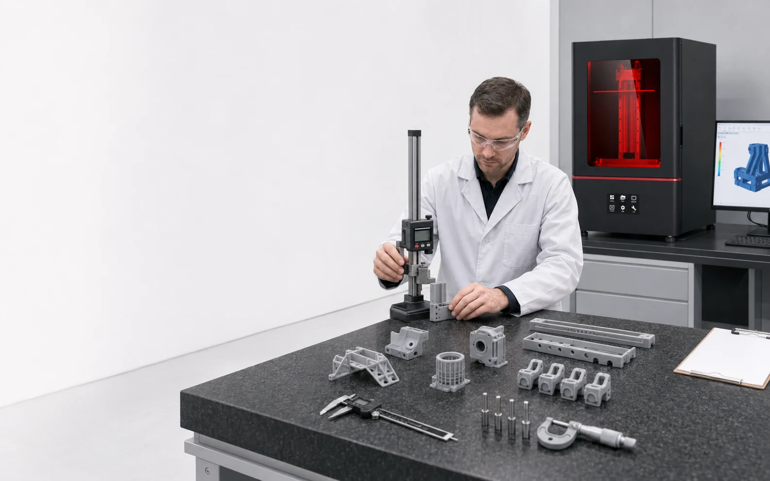
Industrial resin 3D printer accuracy verification workflow
Dimensional verification is a process test, not a printer-only test. Record the variables that can change the result, then hold them stable while comparing builds. When troubleshooting, change one controlled factor at a time where practical.
Release the plan
Lock the nominal files, revision, units, critical characteristics, build layout, quantity, inspection method and acceptance rules.
Confirm equipment condition
Record the printer identity and relevant maintenance or calibration status. Verify the platform, vat, film, optical path and operating environment according to current documentation.
Control the material
Identify the resin and relevant lot or batch information where available. Follow its current TDS, SDS, IFU or other formal instructions for handling and process conditions.
Record build preparation
Save orientation, support strategy, platform position, layer settings, exposure and motion parameters, spacing and any compensation applied.
Print repeated evidence
Use repeated features or parts and more than one build when repeatability matters. Include the platform positions that will be used in normal production.
Complete post-processing
Wash, allow complete drying, perform required UV post-curing and complete specified support removal or finishing according to the material and process documentation.
Inspect consistently
Use the defined datums, instrument, alignment and environmental conditions. Label any intermediate measurement so it is not confused with final acceptance.
Analyze and disposition
Separate nominal bias, repeatability, position effects and feature-specific failures. Record pass, rework, conditional acceptance or reject against the approved rule.
Safety and material control: Do not handle suspected uncured resin as a finished part. Use the exact resin's current safety and processing documents. Cleaning media, drying requirements and UV post-curing conditions are material- and process-specific; they are not universal YIDIMU times.
05 · Measure Correctly
Match the inspection method to the feature and decision
Calipers are useful for accessible external dimensions, but they are not automatically suitable for small internal holes, compliant walls, complex surfaces or tight geometric tolerances. Pin gauges, micrometers, height gauges, optical systems, coordinate-measuring equipment, structured-light scanning or computed tomography may be more appropriate depending on the feature, surface, access and acceptance requirement.
Measurement uncertainty belongs in the plan. If the instrument, alignment or operator method contributes uncertainty comparable to the allowed deviation, a pass/fail result may describe the measurement system as much as the print. Use calibrated equipment, a repeatable fixture where needed and a documented datum or registration method. For 3D scan comparison, distinguish datum-based alignment from global surface-fit alignment: the first answers a functional drawing question, while the second can be useful for overall form but may conceal local interface error.
Read the result in four layers
- Bias: Is a feature consistently larger, smaller, shifted or distorted relative to nominal?
- Repeatability: How much do nominally identical features, parts and builds vary?
- Location effect: Does behavior change between center, edges, corners or height zones?
- Application effect: Does the measured deviation actually prevent fit, assembly, inspection or intended function?
Do not apply one global scale correction to every feature until the pattern is understood. External dimensions, holes, thin walls and long spans can respond differently. A correction that improves one feature may worsen another, and compensation can become invalid when resin, orientation, support strategy or post-curing changes.
06 · Relevant YIDIMU Systems
Industrial systems to evaluate with the same controlled test
The verification method applies to a complete printer–resin–workflow combination. YIDIMU's current public product pages position Eternal M1 and Eternal M2 for industrial resin printing. Their published hardware information can help screen build fit and process requirements, but it should not be converted into a finished-part accuracy guarantee.
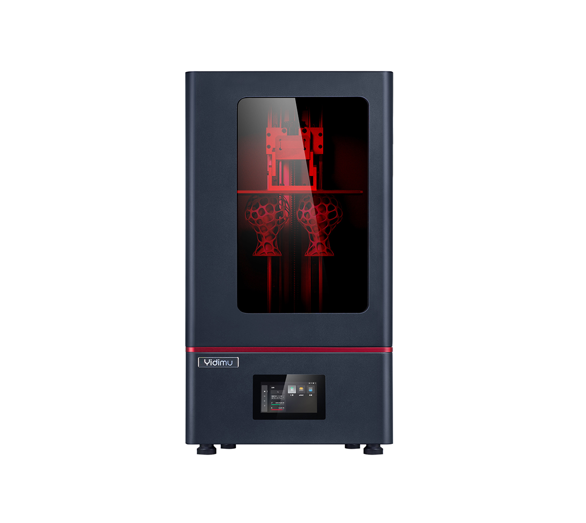
Eternal M1
Evaluate the Eternal M1 with the actual engineering geometry, resin, platform layout, orientation, post-processing sequence and measurement plan required by the project.
View Eternal M1 product information →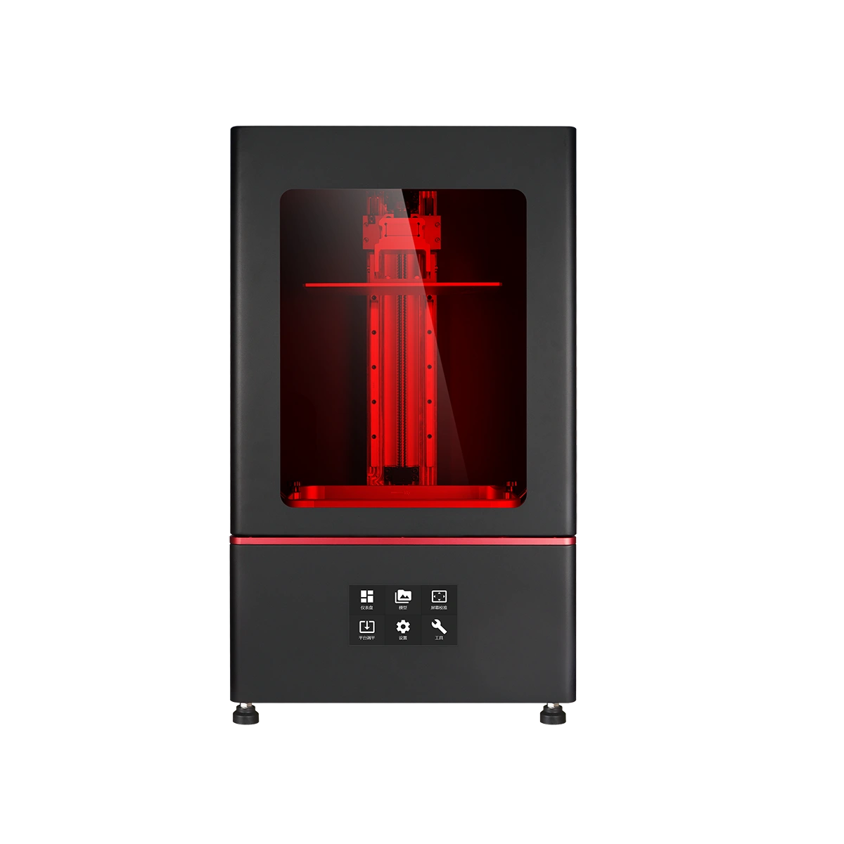
Eternal M2
YIDIMU currently presents the Eternal M2 as a large-format industrial LCD vat-photopolymerization system. Validate usable area, representative large parts and multi-part layouts in their final processed state.
View Eternal M2 product information →Review current photopolymer resin materials and UV post-curing equipment as parts of the same workflow. A nominally matching wavelength alone does not establish material compatibility or finished-part performance.
07 · Practical Evaluation Checklist
Information to prepare for an accuracy-verification request
- Nominal geometry: native CAD or controlled mesh, units, file revision and coordinate system.
- Overall dimensions: oriented size as well as the original part envelope.
- Intended use: appearance review, assembly, fixture, engineering test, flexible component, dental model or other defined task.
- Critical features: datums, holes, slots, bosses, walls, pins, mating surfaces, lattice cells and inaccessible internal geometry.
- Material behavior: required rigidity, flexibility, temperature exposure, surface condition or other documented function.
- Quantity and layout: sample count, expected batch arrangement and platform positions that need evaluation.
- Surface requirements: visible zones, sealing or locating faces, support-sensitive surfaces and allowable finishing.
- Fit and tolerance: drawing limits, mating components, clearance or interference intent and functional pass criteria.
- Post-processing state: washing, complete drying, required UV post-curing, support removal and any allowed finishing.
- Inspection method: measuring tools, datums or alignment, uncertainty needs, report format and disposition rules.
- Repeatability scope: whether evidence is needed within one build, across builds, across platform positions or after a process change.
- Traceability: printer, resin, settings, orientation, operator, post-processing record and measurement record needed for comparison.
08 · Limitations and Validation
A verification result is specific to the tested process
A successful artifact or representative part supports the tested combination of machine condition, resin, model, orientation, supports, platform position, exposure and motion settings, environment, washing, complete drying, UV post-curing, finishing and measurement method. It does not prove the same result for every geometry, material or production condition.
Specification tables remain useful for screening. Build area determines whether an oriented and supported part can fit; pixel size and layer settings describe elements of the imaging and slicing system; material documents define handling and application boundaries. None of those replaces final-part evidence. When production decisions depend on repeatability, use a validation plan proportionate to risk, include repeated builds and define what changes require review or requalification.
Flexible parts require particular care because contact force, deformation, temperature and time after processing can influence measurement. Dental materials and workflows must remain within their documented intended use. A model resin must not be treated as a permanent intraoral restoration, long-term implant material or automatically compliant with FDA, CE or MDR requirements.
FAQ
Industrial resin 3D printer accuracy verification questions
Can XY pixel size be used as the printer's dimensional tolerance?
No. Pixel size describes nominal sampling at the exposure plane. Finished-part dimensions also depend on optical delivery, resin response, model geometry, orientation, supports, settings, motion, environment, washing, drying, post-curing and measurement.
Is one calibration cube enough to verify accuracy?
No for most industrial decisions. A cube can screen overall scale, but it does not adequately represent holes, walls, datum locations, large spans, platform-position effects, repeatability or the geometry of the real application.
When should a resin print be measured?
Final acceptance should normally be performed in the agreed finished state after the controlled washing, complete drying, required UV post-curing and specified finishing sequence. Intermediate measurements can help locate when dimensional change occurs, but they should be labeled separately.
How many parts and builds are required?
There is no universal number. The quantity should follow the purpose, risk and quality plan. An initial screen may use limited evidence, while repeatability or production qualification requires repeated parts and builds under controlled conditions.
Should test parts be placed only at the center of the platform?
No when the intended workflow uses a wider area. Include center, edge or corner positions relevant to the real layout so spatial variation is not hidden by a center-only result.
Can a 3D scan color map replace feature measurements?
Not by itself. Surface comparison is useful for overall form and warpage, but drawing datums, holes, slots, thicknesses, center distances and mating features need methods suited to those characteristics and their acceptance limits.
Project Evaluation
Submit the evidence needed for a useful accuracy review
Share the model file, overall dimensions, intended application, material behavior, quantity, critical structures, surface expectations, mating or tolerance requirements, planned post-processing state and inspection method. YIDIMU can then review the printer, resin and workflow against the actual project without turning a specification value into a production promise.