Dimensional Metrology · Scan-to-Print Validation

Dimensional Inspection of Scan to Print Parts

Dimensional inspection of scan to print parts should separate errors created during scanning, digital reconstruction, printing and post-processing instead of treating the final deviation as a single printer-accuracy number.

  • Define the nominal reference before scanning
  • Keep scan error separate from print error
  • Use a documented alignment method
  • Inspect after complete post-processing
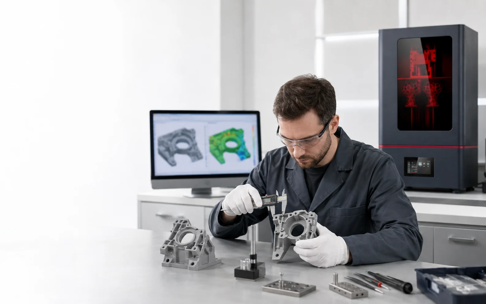
Engineer comparing a fully post-processed resin 3D printed part with CAD and 3D scan inspection data
A useful inspection workflow distinguishes source-scan quality, digital-model preparation, printing and final part measurement.

Direct Answer

How should scan-to-print parts be dimensionally inspected?

Start by deciding what the printed part is supposed to match: the original physical object, an approved CAD model, or a controlled mesh. Qualify the source scan before printing, preserve units and reference geometry, then print with a documented resin, orientation, support and post-processing workflow. Final acceptance measurements should be made after washing, complete drying, required UV post-curing and any defined finishing step. Compare the finished part with the same approved nominal geometry using an alignment method that reflects the functional datums or inspection plan. A full-surface deviation map is useful, but critical dimensions, fit features and tolerances should still be checked with a measurement method whose uncertainty is suitable for the decision.

One deviation has several sources Scanning, mesh processing, printing and post-curing can all change geometry.
Nominal geometry matters An inspection result is only meaningful when the reference model is clearly controlled.
Alignment changes the result Global surface-fit and datum-based registration answer different engineering questions.
Measure the finished state Acceptance should normally follow the complete validated post-processing sequence.
Use representative parts A printer specification does not replace inspection of the geometry you actually need.

01 · Define the chain

A scan-to-print workflow is a chain of geometric transformations

The final printed part can deviate from the source even when every individual stage appears reasonable. The first inspection task is therefore to identify where geometry can change.

STAGE 01 Original part Physical source, master sample or controlled design intent.
STAGE 02 3D acquisition Point cloud or scan data affected by sensor, surface and viewing conditions.
STAGE 03 Digital model Mesh repair, smoothing, hole filling or CAD reconstruction can modify geometry.
STAGE 04 Resin printing Orientation, supports, exposure, mechanics and material behavior affect the build.
STAGE 05 Finished part Washing, complete drying, UV post-curing, support removal and finishing affect the final state.

A common mistake is to scan an object, repair the mesh, print it, rescan the result and report the final cloud-to-cloud difference as “printer accuracy.” That number contains more than printing error. It can include source-scan uncertainty, registration error, mesh changes, scaling, support-related deformation, cure behavior and measurement error from the final inspection.

For engineering work, preserve the raw scan and the approved print file as separate controlled files. If the digital model is intentionally modified—for example, a hole is rebuilt as a true cylinder or a mating face is made planar—the approved CAD or mesh becomes the nominal print reference. The final part should not be judged against an earlier source scan as if no design modification occurred.

02 · Choose the reference

Decide what “correct geometry” means before measuring

Dimensional inspection needs a nominal reference and acceptance criteria. Without them, a deviation map may look precise while answering the wrong question.

Original physical part as the master

Use this approach when reproduction fidelity is the goal and no authoritative CAD exists. Establish independent reference dimensions or features on the original part so the source scan itself can be checked before it becomes the digital master.

Approved CAD as the nominal

Use CAD when the scan is only an input to reverse engineering or when geometry has been redesigned. Dimensions, datums and tolerances should come from the released engineering definition rather than from an uncontrolled scan mesh.

Controlled mesh as the nominal

A mesh can be the production reference when that is the approved deliverable. Freeze the file revision, units, coordinate system and any smoothing or repair operations used before slicing.

Functional fit as an additional criterion

A low average surface deviation does not guarantee that a boss, hole, interface or snap feature will fit. Include feature dimensions, clearances or mating checks that reflect the part's real use.

Important: ISO/ASTM 52902:2023 uses benchmarking artefacts and defined measurements to assess AM-system geometric capability and calibration. The broader lesson for project work is the same: define what is measured, where it is measured and what uncertainty is acceptable before interpreting the result.

03 · Control scan quality

Qualify the input scan before printing

If the source geometry is already distorted, printing can faithfully reproduce the wrong model. The scan should be treated as measurement data, not automatically as ground truth.

Record the scanner, calibration state, acquisition settings, part surface condition, target or marker strategy, number of views and the software used to register the views. Line-of-sight sensors can leave self-occluded areas with incomplete data, and registration can shift when the visible surface does not constrain the pose well. NIST research on CAD-to-point-cloud fitting has shown that registration strategy can materially change alignment residuals for manufacturing-relevant geometries.

Inspect known dimensions on the original part independently when practical. A caliper, micrometer, CMM or other suitable method can provide reference dimensions that help detect scale or reconstruction problems in the scan. Do not use the same unqualified scan as both the source of the nominal model and the only evidence that the model is dimensionally correct.

Mesh processing deserves the same control. Smoothing can soften edges, hole filling can invent surfaces, remeshing can move vertices, and automatic scale or unit conversion can change overall size. Keep a record of intentional modifications and avoid hidden global scaling during inspection merely to make the final part appear to match.

04 · Select the method

Use the measurement method that matches the feature and decision

Dense 3D data is useful for form and surface comparison, but simple feature measurements may be better handled by dedicated dimensional tools.

Method Useful for Strength Main limitations to control
Caliper / micrometer Accessible lengths, thicknesses, diameters and simple feature checks Fast verification of selected dimensions Limited surface coverage, contact force, operator technique and access
CMM Datum-based dimensions, geometric features and controlled feature inspection Structured feature measurement with a defined coordinate system Access, fixturing, probing strategy, time and feature definition
3D scanner Whole-surface comparison, freeform shape, warpage and regional deviation Dense point-cloud or mesh coverage and visual deviation maps Line of sight, surface properties, calibration, registration and filtering
Industrial CT Internal and external geometry where line-of-sight inspection is insufficient Volumetric access to hidden features System suitability, reconstruction, segmentation, uncertainty and cost

Scanner point spacing or nominal sensor resolution should not be treated as measurement accuracy. Calibration, working distance, target surface, field of view, registration, filtering and the software's feature-fitting method all influence the result. When the measurement uncertainty is large relative to the tolerance, a pass/fail decision becomes weak even if the display shows many decimal places.

05 · Control the workflow

A practical workflow for dimensional inspection of scan to print parts

Use one controlled sequence so that geometry, process settings and inspection conditions can be compared across iterations and repeated builds.

Define the acceptance criteria

List critical dimensions, datums, fit interfaces, surface regions, allowable deviations and the final inspection method before the source is scanned.

Establish the nominal reference

Identify whether the master is the original part, approved CAD or controlled mesh. Lock units, coordinate system and revision.

Acquire and qualify the source scan

Document calibration and scan conditions, review coverage, and compare known dimensions or reference features before using the scan for print preparation.

Control mesh or CAD reconstruction

Record smoothing, hole filling, feature reconstruction, remeshing and any intentional compensation. Keep the released print geometry separate from raw scan data.

Freeze the representative print process

Record printer, resin, file version, orientation, supports, process profile, build location and other relevant conditions so the result can be reproduced.

Wash and dry completely

Follow the current material documentation. Residual uncured resin or wash fluid can interfere with surfaces, holes and later inspection.

Complete required UV post-curing

Use the current resin TDS, SDS, IFU or formal process documentation for the selected material and application. Do not invent a universal cure schedule.

Condition and fixture the part consistently

Record relevant environmental conditions and support the part so that measurement setup does not bend or distort flexible or thin geometry.

Align to the correct reference

Use functional datums when the drawing or fit depends on datums. Use global surface-fit only when that is the intended comparison and record the algorithm or settings.

Report features, maps and uncertainty

Record measured values, signed deviations, acceptance result, method, alignment and relevant uncertainty rather than reporting one unsupported “accuracy” value.

06 · Interpret results

Do not let global surface-fit alignment hide the feature that matters

The same scan can produce different deviation maps after different registration choices. Alignment is part of the inspection definition, not a cosmetic software setting.

Feature deviation Measured value − nominal value = signed dimensional deviation

Use signed values when direction matters. A hole that is undersize and a boss that is oversize can both create fit problems even if their absolute deviations are numerically similar.

Surface deviation map Measured surface ↔ approved nominal surface after defined registration

A color map helps reveal bowing, twist, localized bulging and systematic regional error, but it should be interpreted with the alignment method and scale clearly defined.

Global surface-fit registration minimizes a global measure of disagreement between surfaces. That is useful for understanding overall reproduction, but it can distribute error across the part and reduce the apparent deviation at a critical interface. Datum-based alignment instead fixes the part according to the engineering reference frame, which is usually more informative when assembly features or toleranced datums control function.

Also avoid collapsing a complex result into a single average distance. Average values can look small while one wall bows, one interface shifts or one corner lifts beyond the allowed limit. Report the specific features that control acceptance and use whole-surface statistics as supporting information.

07 · Separate process effects

Inspect the final part after the complete resin workflow

Print geometry is not finished when the machine stops. Resin removal, drying, UV post-curing, support removal and finishing can affect the surface or dimensions being inspected.

For acceptance testing, define the stage at which the part becomes “final.” Normally that means the part has completed the approved washing process, is fully dry, has received the required UV post-cure and has undergone the support-removal or finishing operations included in the normal workflow. Intermediate measurements can still be valuable when troubleshooting because they help identify when deformation appears.

Keep material-specific instructions separate. Different photopolymer resins can require different washing, drying and post-curing conditions, so the process should follow the current TDS, SDS, IFU or other formal technical documentation for the exact material. YIDIMU's current English site presents photopolymer materials and UV post-curing equipment as parts of the wider professional resin-printing workflow; suitability for a specific inspection target should still be validated with representative parts.

If repeatability matters, repeat the same inspection across more than one build and, where relevant, across different positions on the usable build area. One successful part cannot establish production repeatability. The test plan should reflect the actual model, material, orientation, support strategy, platform loading and post-processing conditions that will be used in practice.

08 · Relevant systems

Relevant YIDIMU systems for industrial scan-to-print evaluation

Dimensional inspection is an application workflow rather than a model specification. For industrial prototypes, engineering models and larger resin parts, current YIDIMU industrial systems can be evaluated with representative scan-to-print files and a defined inspection plan.

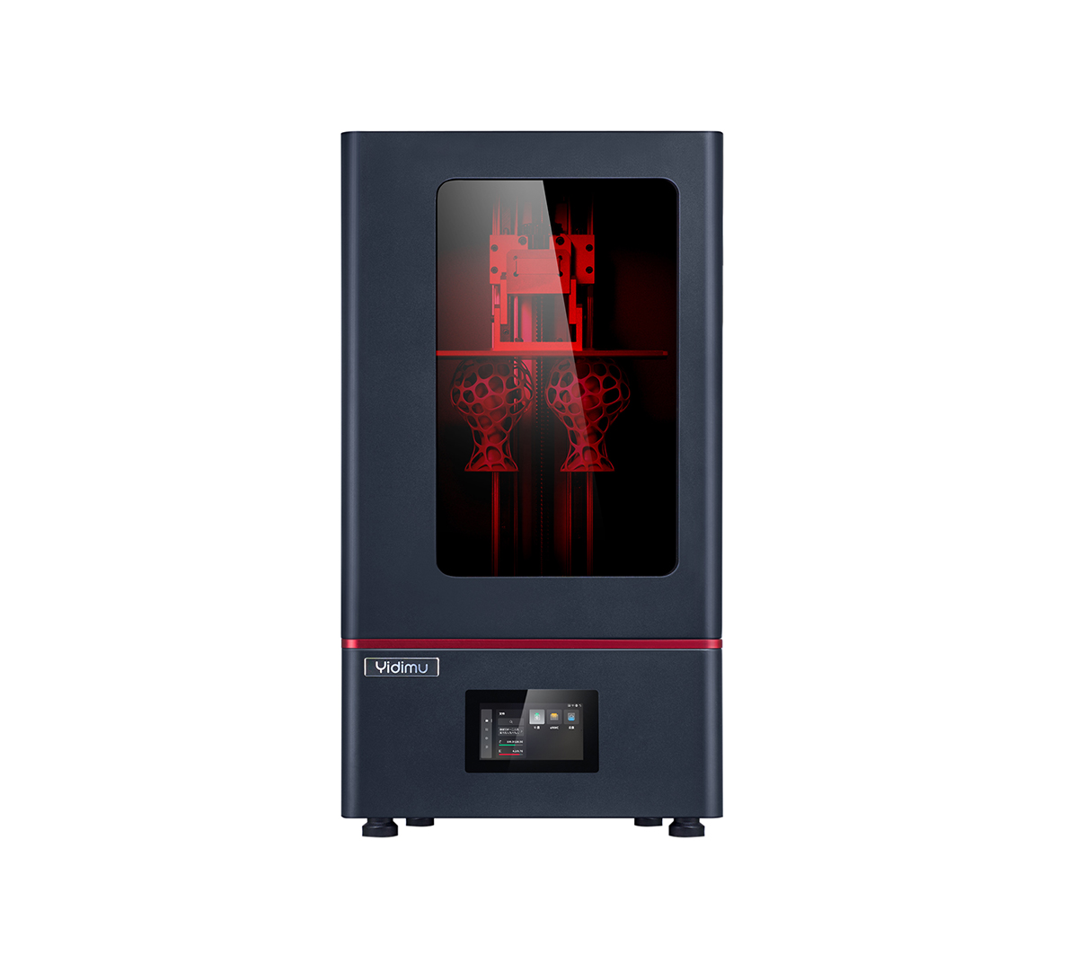
YIDIMU Eternal M1 industrial resin 3D printer

Eternal M1

A current YIDIMU industrial resin 3D printer for professional printing applications. Evaluate it against the actual part geometry, resin, orientation, support and final dimensional inspection criteria required by the project.

View Eternal M1 →
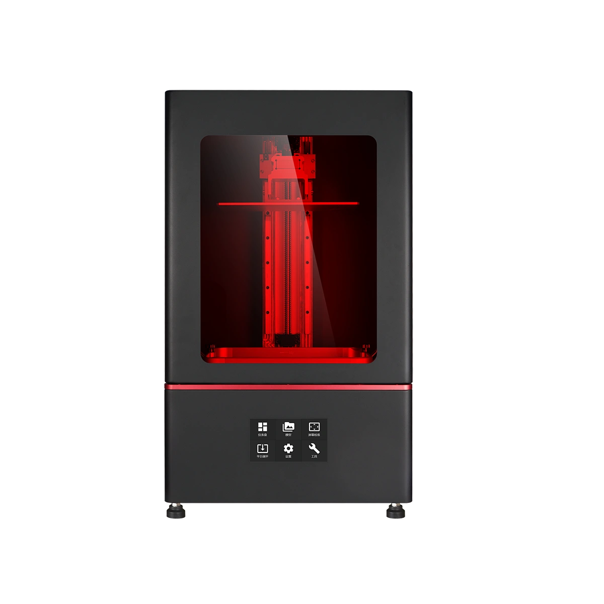
YIDIMU Eternal M2 industrial resin 3D printer

Eternal M2

YIDIMU currently lists Eternal M2 as an industrial light-curing resin 3D printer. Its suitability for a scan-to-print project should be established with the real file and complete post-processing and inspection workflow.

View Eternal M2 →
Printer display resolution, pixel size, layer settings or a supplier accuracy statement should not be used as a substitute for inspecting the representative finished part. The decision should connect the printer, resin, model, build setup, post-processing and measurement method.

09 · Evaluation checklist

Practical scan-to-print dimensional inspection checklist

Use this list when preparing a sample-validation request or an internal engineering test.

  • Original part or approved nominal geometry identified
  • Units, coordinate system and file revision controlled
  • Critical overall dimensions documented
  • Functional datums and mating features identified
  • Required tolerance or acceptance band defined
  • Source scan calibration and acquisition method recorded
  • Mesh repair, smoothing or CAD reconstruction documented
  • Printer, resin and process profile recorded
  • Orientation, supports and build location recorded
  • Washing and complete drying process controlled
  • UV post-curing completed according to current material documentation
  • Support removal and finishing stage defined
  • Inspection method suitable for feature and tolerance
  • Alignment method documented
  • Measurement uncertainty considered in pass/fail decisions
  • Repeat builds included when repeatability matters

10 · Limitations

What dimensional inspection can and cannot prove

A well-designed inspection can quantify the tested workflow. It does not automatically prove universal performance for every geometry, resin or production condition.

Scan-to-print validation is specific to the chosen nominal reference, scanner, digital processing, printer, resin, orientation, support design, exposure profile, environmental conditions, washing, drying, UV post-curing and inspection method. Changing one of these can create a new process condition that needs review.

A scanner's specification, a printer's screen resolution and a single successful sample are screening evidence—not a production guarantee. For parts with critical fit or dimensional requirements, use representative geometry and repeat the process under conditions that resemble normal production. If internal features, flexible sections, thin walls or large unsupported surfaces matter, select an inspection strategy that can actually observe those features without adding excessive measurement uncertainty.

FAQ

Dimensional inspection of scan-to-print parts: common questions

Should a resin 3D printed part be measured before or after UV post-curing?

Final acceptance should normally be performed at the defined finished state, after the approved washing, complete drying, UV post-curing and finishing sequence. Intermediate measurements can be useful for diagnosing when dimensional change occurs.

Can a 3D deviation color map replace dimensional measurements?

Not by itself. A color map is useful for whole-surface form and warpage, but critical holes, datums, mating features, thicknesses and toleranced dimensions should be evaluated with methods appropriate to those features.

Is global surface-fit alignment suitable for every scan-to-print inspection?

No. Global surface-fit alignment is useful for overall shape comparison, but datum-based alignment is usually more meaningful when functional interfaces or drawing datums control how the part assembles or is accepted.

How can scan error be separated from print error?

Qualify the source scan against independently known dimensions or reference features before printing, preserve the raw scan, and inspect the finished print against the approved nominal model. This prevents all upstream error from being mislabeled as printer error.

Does scanner resolution determine dimensional measurement accuracy?

No. Resolution or point spacing is only one specification. Calibration, surface condition, working geometry, registration, filtering, feature fitting and measurement uncertainty also affect the dimensional result.

How many printed parts should be inspected?

There is no universal number. A development check may begin with one representative part, while repeatability or production validation requires repeated parts and builds selected according to the project's quality plan and risk.

Related resources

Continue the process-control review

Resin 3D Printer Light Uniformity Understand why exposure consistency is one process variable behind feature reproduction and repeatability. Large-Format Resin 3D Printer for Industrial Parts Plan orientation, supports, post-processing and inspection for larger engineering geometry. Resin 3D Printing for Low-Volume Manufacturing Connect representative-part testing with batch layout, inspection and accepted output. Photopolymer Resin Materials Review current material categories and confirm the selected resin through current technical documentation. Post-Processing Equipment Review YIDIMU UV curing and supporting equipment for controlled resin workflows. Resin 3D Printing Resource Center Browse current technical guides on equipment evaluation, process control, capacity and application validation.

Project Evaluation

Submit the scan-to-print part you actually need to validate

Share the model file or approved nominal geometry, overall dimensions, critical features, material requirement, quantity, surface expectations, fit requirements and intended inspection method. If the project begins from a physical source part, also explain how the source was scanned and which dimensions or datums must be preserved. YIDIMU can use this information to discuss a suitable printer, resin, post-processing workflow and representative sample-evaluation approach without assuming a fixed result before testing.

Submit Project Requirements View Industrial 3D Printers