Industrial Resin Printing · Process Selection

SLA vs DLP vs LCD for Industrial 3D Printing

SLA, DLP and LCD/MSLA all cure liquid photopolymer resin, but they create each layer image in different ways. For industrial 3D printing, that difference matters because it changes the optical architecture, scaling behavior, maintenance points and the questions you should ask during sample validation.

  • Laser scanning vs projected image vs masked image
  • Build-area and XY sampling tradeoffs
  • Throughput must include the full layer cycle
  • Finished-part validation outranks a technology label
Engineer evaluating resin 3D printing exposure technologies for industrial parts
Compare the exposure system and the complete production workflow, then validate representative parts.

SLA vs DLP vs LCD for industrial 3D printing is not a simple ranking. All three are forms of vat photopolymerization. Laser-based SLA scans each layer with a focused beam; DLP uses a projector to form a layer image; LCD/MSLA uses an LCD as a programmable mask between a light source and the resin. Those exposure methods affect how XY detail is generated, how the optical system scales across a build area and what components require calibration or maintenance. They do not, by themselves, prove finished-part accuracy, speed or production suitability. Industrial selection should be based on the actual part, resin, build layout, layer cycle, post-processing and measured sample results.

Same process familyAll three selectively cure liquid photopolymer in a vat.
Different image formationSLA scans; DLP projects; LCD masks.
No universal speed winnerExposure is only one part of each layer cycle.
Resolution is not accuracyPixel, spot or layer values are incomplete evidence.
Validate the partRepresentative geometry and inspection should decide suitability.

What actually changes between SLA, DLP and LCD/MSLA?

The shared principle is selective photopolymerization. A sliced model is converted into two-dimensional cross-sections, and the printer cures one cross-section after another. The practical difference is the light engine that creates the exposure pattern.

01

Laser-based SLA

A focused laser is directed across the resin to trace the geometry required for the current layer. Industrial evaluation therefore needs to consider scan-field calibration, spot behavior, path strategy, optical alignment and whether performance changes across the usable area.

02

DLP

A digital projector forms the layer image, typically using a micromirror-based imaging device and projection optics. Relevant questions include projected pixel size, focus, distortion, irradiance distribution and how optical magnification changes when the projected area increases.

03

LCD / MSLA

An LCD panel acts as a dynamic mask while light from an LED-based source passes through selected pixels. The physical pixel pitch, panel size, optical collimation, light uniformity, heat management and screen condition all matter to the printing system.

Comparison point Laser SLA DLP LCD / MSLA
How the layer is formed Focused laser scans the required geometry Projector displays the layer image LCD mask controls where light passes
Primary XY consideration Spot behavior, scan positioning and optical field Projected pixel size, focus and magnification Physical pixel pitch, mask behavior and optical delivery
Exposure scaling Scanning workload can vary with geometry Layer image is exposed in parallel, but optics and area still matter Layer image is exposed in parallel through the mask, but panel and light system still matter
Industrial validation focus Scan-field consistency and representative features Projection quality across the build field Mask/light uniformity and repeated parts across the build field
Terminology caution: “SLA” is sometimes used loosely for resin printing as a whole. For equipment comparison, ask how the layer is actually exposed rather than relying on the marketing label alone.

SLA vs DLP vs LCD for industrial 3D printing: the questions that matter

1. What happens when the build area becomes larger?

A technology that works well on a small build area still has to maintain optical and mechanical control when scaled. In DLP, the same projector image spread over a larger area can increase projected pixel size unless the imaging system changes. In LCD/MSLA, panel dimensions and total pixel count together determine nominal physical pixel pitch. In laser SLA, the scan field, spot behavior and optical calibration must be controlled over the required area.

None of those values should be treated as an automatic accuracy claim. For large industrial housings, engineering models or multi-part builds, measure the same critical features at several positions across the usable platform. YIDIMU's resource on resin 3D printer light uniformity explains why center-only checks can miss process variation.

2. Does parallel layer exposure make DLP or LCD automatically faster?

No. DLP and LCD/MSLA can expose a selected layer image in parallel, while laser SLA traces geometry. But completed build time also includes platform motion, layer separation or recoating, resin refill or leveling behavior, temperature, layer count and any pauses built into the process. Adding more parts to the same DLP or LCD layer may not increase image exposure time in the same way it changes a scanned path, yet the larger loaded area can still affect separation forces and resin flow.

For industrial planning, compare accepted parts per build or per shift using your real geometry. A nominal exposure time or vertical speed does not represent the full production cycle.

3. Which technology gives the highest dimensional accuracy?

There is no defensible universal answer from the technology name alone. Finished dimensions depend on the full system: optical calibration, mechanical stability, resin cure behavior, exposure settings, geometry, orientation, supports, temperature, washing, complete drying, UV post-curing and the inspection method. A smaller LCD pixel, smaller projected pixel or smaller laser spot can describe part of the imaging system, but it does not independently establish the accuracy of a finished industrial part.

If your project has controlled holes, mating faces, wall thicknesses or assembly interfaces, define those features on the drawing and measure them after the complete post-processing sequence. For a related explanation, see 8K vs 12K vs 16K resin 3D printers.

4. How do maintenance priorities differ?

The maintenance burden follows the machine architecture. Laser systems depend on the condition and calibration of the laser delivery path and motion or scanning components. DLP systems depend on projector optics, focus, alignment and light-output consistency. LCD systems add a transmissive screen that functions as the mask, so panel condition and the light-delivery system become important process-control points.

All three also depend on common vat-photopolymerization maintenance: build-platform condition, vat or release-interface inspection where applicable, resin handling, contamination control, motion-system checks, cleaning practices and post-processing equipment. Maintenance should therefore be planned around the actual system rather than a generic percentage of purchase price. See the industrial resin 3D printer maintenance cost guide for a usage-based framework.

5. Is the exposure technology compatible with the resin you need?

The nominal wavelength is only one compatibility factor. Resin cure depth, absorption, pigmentation, viscosity, temperature sensitivity, separation behavior and required post-curing conditions also influence the usable process window. For any material, use the relevant TDS, SDS, IFU or other formal technical document for handling and processing requirements.

Choose by the manufacturing task, not by the acronym

Project requirement What to examine Why the technology label is insufficient Practical validation
Large single part Usable build area, support strategy, optical consistency, separation or recoating behavior Nominal build volume does not prove edge-to-edge dimensional control Print the real envelope or a representative large section and inspect multiple zones
Dense multi-part batch Nesting, layer cross-section, release forces, resin refill, post-processing capacity Parallel exposure does not remove mechanical and material constraints Run the intended batch layout, not a single demonstration part
Fine holes and mating features Optics, exposure, compensation strategy, resin, orientation and measurement method Pixel or spot size does not equal hole or fit accuracy Measure the actual controlled features after final curing
Flexible or elastomer part Material documentation, support behavior, peel/separation loads, post-cure requirements Material behavior can dominate the process more than exposure architecture Test the intended lattice, wall section, bending zone or cushioning geometry
Low-volume production Accepted parts per build, labor, wash/dry/cure capacity, inspection and reprints Printer-only cycle time omits downstream bottlenecks Track complete workflow time and accepted output

When laser SLA may deserve closer evaluation

  • Your application benefits from a scanned optical architecture and the available system meets the required build field.
  • You can verify scan-field consistency, spot behavior and calibration on representative geometry.
  • The resin, recoating or separation method and post-processing workflow are documented for the intended use.

When DLP or LCD/MSLA may deserve closer evaluation

  • Your workflow values image-based layer exposure for one or multiple parts in the same layer.
  • The projected or masked pixel scale is suitable for the required build area and feature sizes.
  • You can verify light distribution, optical consistency, separation behavior and repeatability across the usable platform.
Do not treat these as selection rules. They are screening questions. Two machines that use the same exposure family can produce different results because their optics, mechanics, thermal control, resin profiles, software and post-processing workflows differ.

The printer is only one station in an industrial resin workflow

Technology comparisons often stop at the light engine. Industrial decisions should continue through the point where a part is clean, fully dry, post-cured as required, finished and inspected. A printer can have suitable optical specifications and still be a poor production fit if downstream capacity or process control is inadequate.

STEP 01Prepare

Check model dimensions, orientation, supports, drainage and critical surfaces.

STEP 02Print

Use the validated printer, resin and parameter set for the representative job.

STEP 03Wash & fully dry

Follow the material instructions and ensure cleaning fluid is removed before curing.

STEP 04UV post-cure

Use the material-specific wavelength, time and temperature requirements where applicable.

STEP 05Finish

Remove supports and perform only the finishing needed for the intended evaluation.

STEP 06Inspect

Measure controlled dimensions and examine surfaces, fit and defects.

STEP 07Repeat

Run additional builds when repeatability or batch consistency is important.

STEP 08Approve

Approve the process only against defined acceptance criteria for the real application.

For larger parts and multi-part layouts, also review large-format resin 3D printing for industrial parts. For production planning, see resin 3D printing for low-volume manufacturing.

Industrial LCD systems to evaluate against representative parts

YIDIMU's current industrial product pages present Eternal M1 and Eternal M2 as LCD/light-curing industrial 3D printers. Their relevance to a project should be confirmed from part dimensions, material requirements, quantity, surfaces, fit criteria, post-processing and sample results rather than from the LCD label alone.

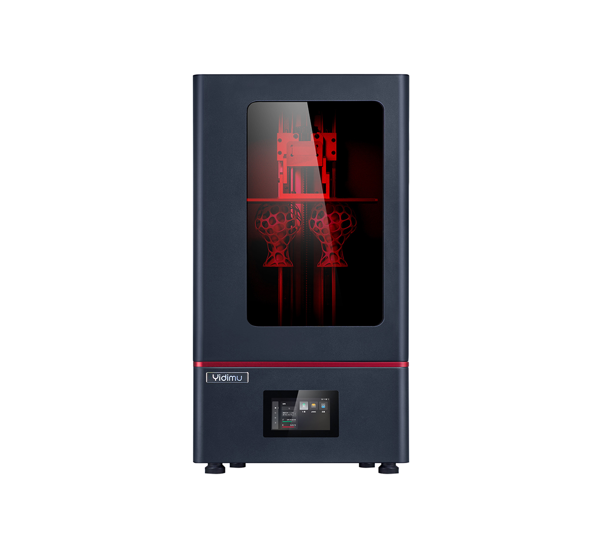
YIDIMU Eternal M1 industrial LCD resin 3D printer
Eternal M1 — industrial LCD resin 3D printer.

Eternal M1

The current product page identifies Eternal M1 as an industrial-grade light-curing printer using a 13.6-inch 7K screen. For project evaluation, confirm the actual supported part layout, resin choice, critical dimensions and post-processing workflow.

View Eternal M1 →
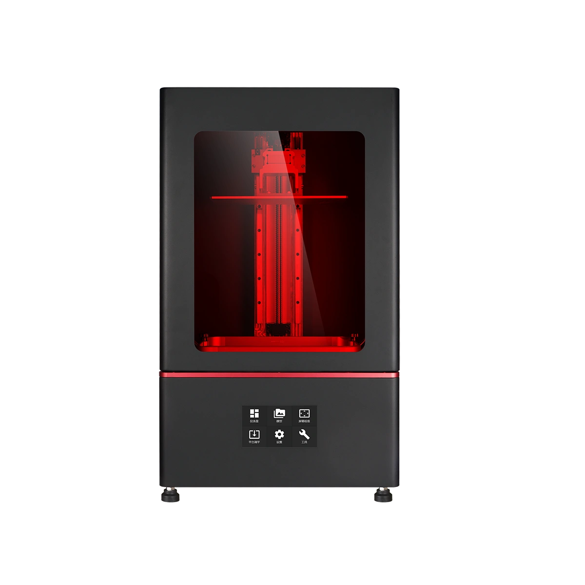
YIDIMU Eternal M2 industrial LCD resin 3D printer
Eternal M2 — industrial LCD light-curing system.

Eternal M2

The current product page identifies Eternal M2 as an LCD light-curing industrial printer and lists a 16-inch printing area. Use representative parts to verify the usable build layout, dimensional behavior and downstream processing required by the application.

View Eternal M2 →

What to send or measure before choosing a resin printing system

  • Overall dimensions: maximum X, Y and Z after realistic orientation and supports.
  • Application: appearance model, engineering validation, flexible part, fixture, dental model or low-volume part.
  • Critical geometry: holes, walls, channels, text, edges, bosses, ribs and unsupported spans.
  • Material behavior: rigidity, flexibility, heat exposure, impact, rebound, casting or surface needs.
  • Quantity: parts per build, expected batches and production frequency.
  • Surface zones: cosmetic faces, support-sensitive surfaces and areas that can be finished.
  • Fit requirements: mating faces, assembly clearances and controlled interfaces.
  • Tolerances: dimensions that have acceptance limits and the method used to measure them.
  • Post-processing: washing, complete drying, support removal, UV post-curing and finishing capacity.
  • Inspection plan: caliper, gauge, scanner, CMM or other suitable method for the required feature.
Validation limit: a generic benchmark or display sample cannot prove that your own large flat panel, thin wall, internal channel, flexible lattice or tight assembly interface will perform the same way. Use a representative part and repeat the test when process consistency matters.

Continue the evaluation with focused process guides

Resin 3D Printer Light UniformityHow to evaluate spatial exposure consistency across the usable build plane. 8K vs 12K vs 16K Resin 3D PrinterWhy screen resolution alone does not establish finished-part accuracy. Large-Format Resin 3D Printer for Industrial PartsPlan large housings, engineering models and multi-part industrial builds. Industrial Resin 3D Printer Maintenance CostBuild a maintenance model around usage, consumables, labor and downtime. Resin 3D Printing for Low-Volume ManufacturingEvaluate accepted-part output across printing and downstream operations.

SLA vs DLP vs LCD industrial 3D printing FAQ

Is LCD 3D printing the same as SLA?

Not in strict technical usage. Laser-based SLA scans a focused beam across each layer. LCD/MSLA uses an LCD as a programmable mask while a separate light source exposes selected areas.

What is the main difference between DLP and LCD resin printing?

DLP creates the layer image with a projector, commonly using a micromirror-based imaging device. LCD/MSLA creates the mask with a transmissive LCD panel. Both can expose a layer image in parallel, but their optical architecture and scaling behavior differ.

Is DLP always faster than laser SLA?

No. DLP can expose a layer image in parallel, but total build time also includes layer movement, separation or recoating, resin flow, part height, layer count and other machine-specific steps.

Does a higher-resolution LCD automatically make more accurate parts?

No. LCD resolution affects nominal pixel pitch, but final dimensions also depend on optics, exposure, resin, mechanics, geometry, support strategy, post-processing and calibration.

Which technology is better for large industrial parts?

There is no universal answer. Compare the usable build area, optical consistency across that area, support and separation behavior, resin workflow, post-processing capacity and measured results from a representative large part.

What should I test before buying an industrial resin printer?

Test the geometry you actually need: overall size, thin walls, holes, mating features, visible surfaces and the intended material. Process it through washing, complete drying and required UV post-curing, then measure the acceptance features and repeat the build if consistency is important.

Apply the technology comparison to your actual part

Send the model file, overall dimensions, intended application, material requirements, quantity, surface expectations, critical fits and inspection requirements. Those details are more useful for equipment selection than asking whether SLA, DLP or LCD is better in the abstract.

Submit Project Requirements View Industrial 3D Printers