
Choose the primary datum
Select the functional surface or feature that should establish the part’s main orientation in the assembly.
Engineering Design · Jigs & Production Aids
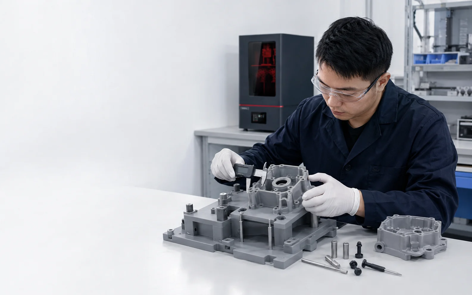
A useful assembly jig starts with the part datum and the real assembly sequence—not with the printer. Design the locating scheme, access, clearance, clamping and inspection method first, then validate the printed jig after the complete resin post-processing workflow.
Direct Answer
Design a 3D printed assembly jig around the features that must control the assembly: the primary datum, secondary and tertiary locating features, component insertion path, allowable movement, operator access, clamp direction and final inspection points. Use only the constraints needed to establish a repeatable position, because unnecessary contact points can make loading difficult or force inconsistent parts into the wrong position. For resin-printed jigs, include the printing and post-processing workflow in the design review. Critical dimensions, holes, nests and fit surfaces should be evaluated after washing, complete drying, support removal as applicable, UV post-curing and final inspection—not immediately after the build finishes.
Start from the assembly requirement and datum structure rather than copying the full part surface.
Separate locating features from clamping features so the clamp does not define the part position.
Provide loading clearance, finger access, tool access and a deliberate removal path for the assembled part.
Orient supports away from critical datum and mating surfaces whenever the print strategy allows it.
Approve the jig with representative components, the real assembly sequence and written acceptance checks.
01 · Functional Definition
An assembly jig is useful when it makes a positioning or assembly task more repeatable, easier to perform or easier to inspect. A fixture primarily holds and locates a workpiece; a jig may also guide a tool, component or assembly action. In practice, a printed production aid can combine both functions, so the important question is not the label. The important question is what motion must be controlled.
Before modeling the jig body, write down the assembly sequence. Which component enters first? Which faces establish position? Which feature must remain visible? Where does an operator need to press, fasten, bond, insert or inspect? What force is applied during the operation? A jig that locates a component accurately but blocks the screwdriver, connector, adhesive nozzle or inspection probe is not ready for the production floor.
A one-time fit can hide a poor locating scheme. A better acceptance statement identifies which surfaces contact the jig, which feature establishes orientation, how the component is clamped and what measurement or functional check confirms the assembled result.
If several part revisions use the same jig, identify which interfaces are intentionally common and which should be modular or replaceable.
02 · Locating Strategy
A rigid part can move in six degrees of freedom: translation along three axes and rotation around those axes. A locating scheme removes the unwanted motion in a controlled order. For many rigid prismatic components, the familiar 3-2-1 approach is a useful starting framework: three contacts establish a primary plane, two establish a secondary direction and one establishes the remaining position. The exact arrangement should follow the actual functional datums of the assembly rather than being applied mechanically to every geometry.
Keep locator contact areas deliberate and accessible. Small pads, pins, shoulders, nests and hard stops are easier to reason about than a large organic cavity that contacts the workpiece everywhere. Full-surface nests can be appropriate for fragile or complex components, but they also make dimensional variation, contamination and post-cure distortion harder to diagnose.
Select the functional surface or feature that should establish the part’s main orientation in the assembly.
Add secondary locators that control side-to-side position while preserving a simple loading path.
Use a final stop, pin or face to define the remaining position without adding redundant constraints.
Direct clamp force toward supported areas and locators rather than across unsupported thin walls.
Confirm the operator can insert and remove parts naturally without prying against fragile printed features.
Leave access for calipers, pins, gauges, visual checks or functional mating parts used at release.
03 · Clearance, Access & Error Prevention
Nominal CAD geometry is not a reliable clearance value by itself. The required gap between a printed locator and a production component depends on the component tolerance, resin behavior, print orientation, support strategy, post-processing and the measurement method. Instead of copying a generic clearance number, define the required function: slip placement, light retention, controlled press, alignment before fastening or a deliberate no-go condition. Then establish the final dimension through representative printed samples.
Use chamfers, lead-ins and open-sided nests where they help operators load the correct feature without searching for the position. If a component can be installed backwards or rotated incorrectly, add asymmetric stops or a shape cue that makes the wrong orientation physically difficult or visually obvious. These features can be integrated into the printed body without adding separate hardware.
Finger scoops, pickup reliefs and open windows can make a jig easier to use than a tight cavity. Add escape space where dust, chips, cured resin residue or part flash could otherwise accumulate under a datum. Do not let contamination become an unintended locator.
04 · Strength, Wear & Replaceable Features
A resin jig can be suitable for positioning, assembly support, inspection aids and other production tasks when the material and geometry are validated for the actual load and environment. Do not treat a material name such as “rigid” or “ABS-like” as proof of load capacity, wear life, heat resistance or chemical compatibility. Those requirements need current technical documentation and application testing.
Increase stiffness where deflection would move a critical locator: shorten cantilevers, add ribs, use generous fillets at load transitions and support clamp reaction points. At the same time, avoid simply making the entire tool solid. A well-ribbed shell can be easier to handle and can reduce unnecessary resin use while keeping the important load paths stiff.
For high-contact pins, threaded interfaces, drill-guiding surfaces or repeated wear points, consider whether a metal pin, insert, bushing or replaceable printed insert is more appropriate than exposing the printed resin directly. The decision should follow the actual duty cycle and contact condition rather than a fixed rule.
05 · Resin Printing Design
The jig CAD model and the manufacturing plan should be reviewed together. Orientation changes the supported surfaces, separation behavior, build height and the way critical features are formed. Place support contact away from locating pads, gauge faces and other surfaces that directly control the assembly whenever practical. If a critical feature must face a less favorable direction, decide how it will be finished and inspected before printing.
Hollowing, drainage and enclosed cavities require the same discipline. A cavity that cannot be washed and completely dried can retain contamination and complicate post-curing. If the jig includes internal channels, blind pockets or deep nests, confirm that the cleaning method can reach them and that the part can be verified dry before UV post-curing.
Use the resin’s current TDS, SDS, IFU or other formal technical documents for handling, compatible cleaning method and post-curing conditions. Wear suitable protective equipment when handling uncured resin or contaminated cleaning media. Final jig dimensions should be checked only after the approved post-processing sequence is complete.
| Design decision | What to review | Why it matters | Validation method |
|---|---|---|---|
| Datum surfaces | Support contact, orientation, accessibility | These features define assembly position | Measure after full post-processing and test with representative parts |
| Locator clearance | Part tolerance, resin process, intended fit | Too tight can prevent loading; too loose can reduce repeatability | Print controlled variants and measure functional fit |
| Clamp points | Load path, wall stiffness, reaction support | Clamp force can shift or deform the workpiece | Observe movement under the real assembly load |
| Wear interfaces | Contact pressure, cycles, friction, heat | Printed surfaces may not be suitable for every repeated contact | Cycle test or use replaceable inserts where needed |
| Internal cavities | Drainage, washing, complete drying, UV access | Trapped residue can compromise the workflow | Inspect cleanliness and dryness before post-cure |
| Inspection features | Probe, gauge and visual access | A jig must be verifiable, not merely usable | Apply a written inspection plan to the finished tool |
06 · Prototype to Production Aid
Do not approve an assembly jig from CAD screenshots or a dimensional report alone. The finished tool should be tested with representative production components and the actual sequence used on the floor. If incoming components vary, include samples near the expected tolerance boundaries rather than testing only the easiest part.
Measure the jig’s critical locating features, then perform the assembly. Check loading effort, seating, clamp behavior, tool access, visibility, removal and the final assembled condition. A dimensional pass does not automatically prove ergonomic or process suitability, and a successful assembly does not automatically prove repeatable location. Both need to be reviewed.
If the jig will be printed repeatedly, keep a controlled master file, identify the approved orientation and support approach, and record the resin and post-processing route used for validation. A change in resin, orientation, support layout, cure process or critical geometry can justify revalidation.
07 · Relevant YIDIMU Systems
Assembly jigs, positioning tools and engineering aids belong to the same broader industrial prototyping and production-support workflow as other functional resin-printed models. For a specific jig, equipment selection should begin with the oriented tool size, the required material behavior, the number of tools per build, post-processing capacity and the inspection plan.
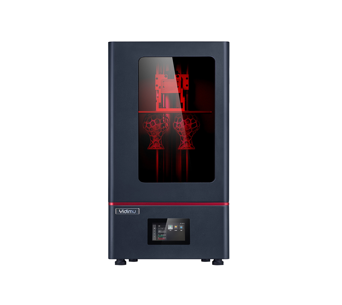
Use the M1 as a candidate system when evaluating industrial resin workflows for prototypes, engineering models and production aids. Confirm the current machine configuration, resin choice and representative jig results for the specific project.
Review Eternal M1 →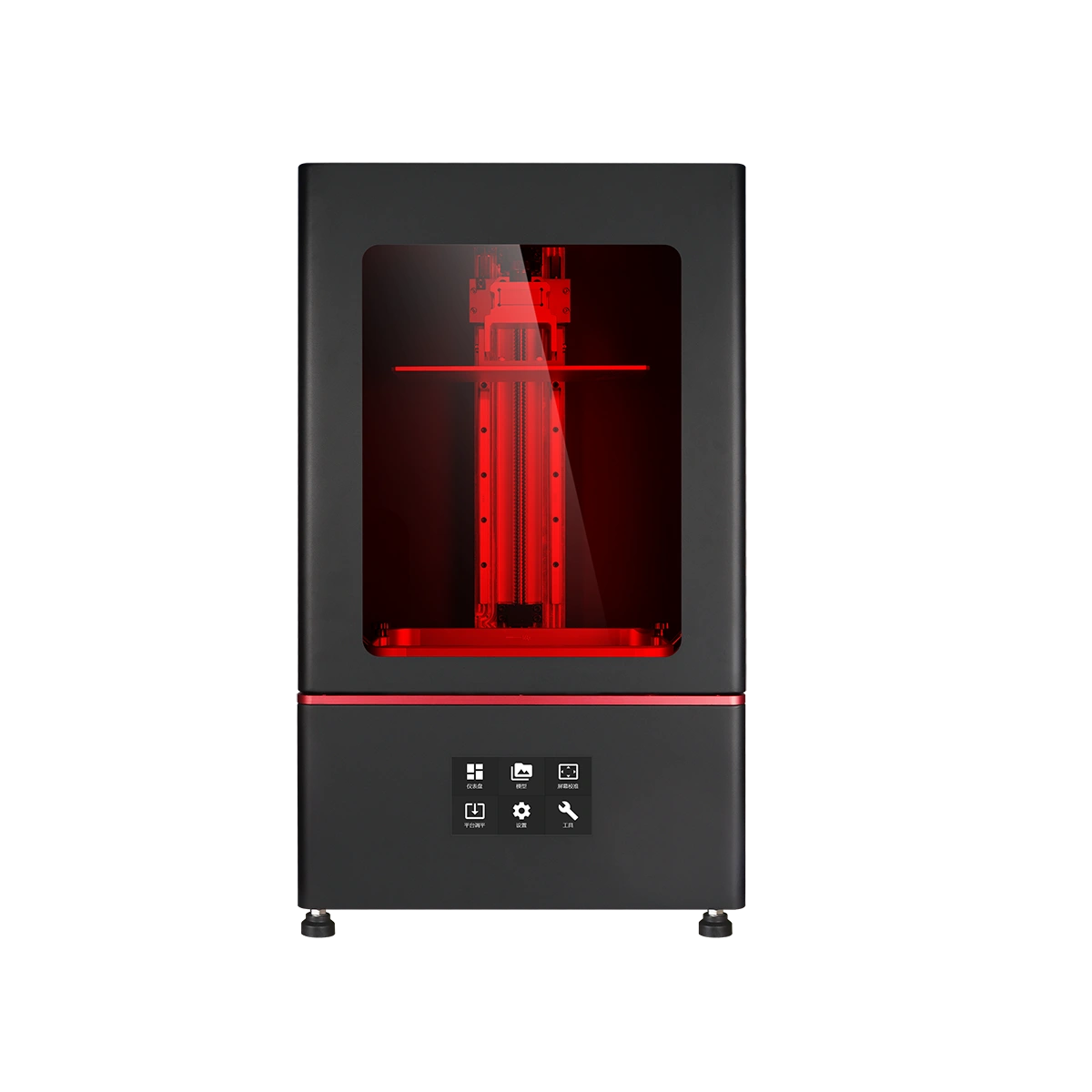
The M2 is relevant when a larger assembly jig, longer tool body or multi-jig layout requires a larger industrial build format. Evaluate the supported orientation and complete post-processing workflow rather than the nominal build envelope alone.
Review Eternal M2 →08 · Practical Evaluation Checklist
Use a written checklist that connects the CAD intent to the finished tool and the actual assembly operation.
09 · Limitations & Validation
Printer resolution, resin category and nominal build size do not establish assembly-jig performance by themselves. Final behavior depends on the exact machine, material, model geometry, orientation, supports, exposure settings, environment, washing, complete drying, UV post-curing, finishing and measurement method.
For dimension-critical, load-bearing, high-cycle, heat-exposed or chemically exposed jigs, define acceptance requirements before choosing the resin. Request the current technical documentation and test the representative tool under the real assembly condition. Production release should be based on measured results and functional validation rather than a generic material label or a single successful print.
10 · Common Questions
A fixture primarily locates and holds a part. A jig can also guide a tool, component or assembly action. Many printed production aids combine both functions, so define the required motion control and workflow rather than relying on the name alone.
There is no single clearance that works for every resin jig. The required value depends on the production-part tolerance, intended fit, printer, resin, orientation, supports and post-processing. Validate clearance with measured test variants and representative components.
Usually only the functional locating and support regions need controlled contact. Large full-surface nests can be useful for some fragile or complex parts, but they can also make variation, contamination and dimensional errors harder to diagnose.
They can be printed for some low-demand uses, but repeated wear, tightening load or tool contact may justify metal inserts, pins or bushings. Decide from the actual load, cycles and wear requirement.
Measure critical features after the validated workflow is complete: printing, washing, complete drying, necessary support removal, UV post-curing and any planned finishing. Measuring only the fresh print can misrepresent the final tool condition.
Provide the jig or component model, overall dimensions, intended assembly task, critical datums, required material behavior, quantity, surface requirements, fit or tolerance concerns, post-processing expectations and the inspection method you plan to use.
Related Resources
Project Evaluation
Share the model file, overall dimensions, assembly task, critical datums, material requirements, quantity, surface expectations, fit or tolerance concerns and the inspection method. The goal is to review the complete print and post-processing route against the real jig function.