
Application Validation
3D Printed Elastomer Parts: How to Specify, Measure and Validate Them
Soft parts fail acceptance for different reasons than rigid ones. This guide covers how to write a usable specification, how to measure geometry that deforms under the gauge, and which properties have to be tested separately.
- Hardness, stiffness, rebound and compression set are four different properties with four different test methods.
- Screen resolution and pixel size describe the exposure system, not the dimensional behaviour of a finished part.
- Soft geometry deforms under contact gauges, so measurement method has to be written down before numbers mean anything.
- Parts must be washed, completely dried and UV post-cured before any hardness or dimensional reading is recorded.
- Decisions come from the spread across a batch, not from one accepted sample.
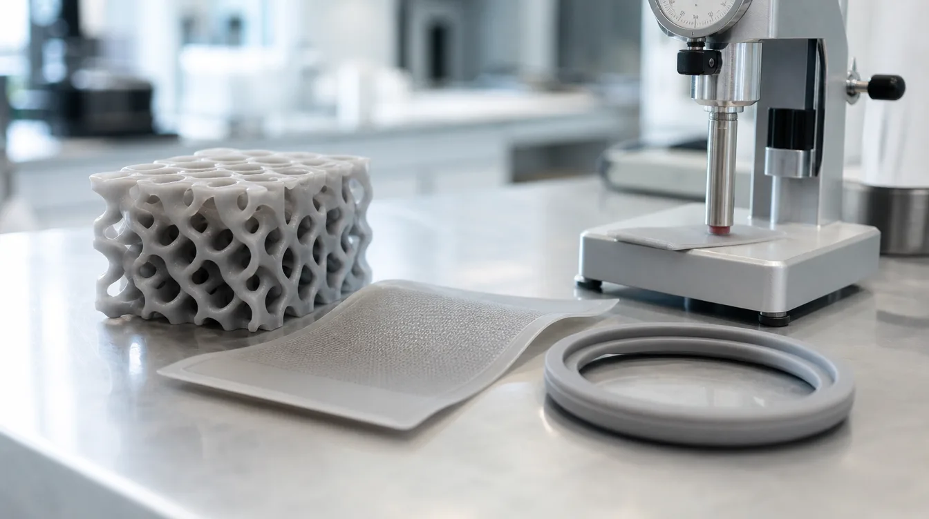
Direct answer
3D printed elastomer parts are accepted or rejected on function, not on the exposure specification of the printer. A usable requirement names four things: the hardness scale and durometer type, the small set of dimensions that actually control fit, the deformation the part has to survive and recover from, and the condition the part is in when it is measured — washed, completely dried and UV post-cured. Soft geometry deflects under a caliper or a touch probe, so dimensional checks usually move to non-contact scanning with a defined support and a defined conditioning period. Hardness, rebound and compression behaviour are separate properties and need separate methods. Print a batch, measure it under one written procedure, and judge from the spread.
Key takeaways
- A hardness number without a scale and durometer type is not a specification.
- Apparent part hardness is influenced by wall thickness and lattice design, not only by the resin.
- Contact measurement of soft parts reads low or high depending on operator force; the method must be fixed and recorded.
- Molded-rubber tolerance frameworks describe molding control levels and do not transfer to printed parts as an acceptance promise.
- Resolution and XY pixel size describe the light engine; accuracy is a property of the finished, post-processed part.
- Elastomer validation is incomplete until the part has been loaded the way it will be loaded in service.
Four properties that get confused with each other
Most disagreements about elastomer samples come from treating "soft" as a single value. Softness on a durometer, resistance to deflection in a structure, how quickly a part returns to shape, and how much shape it permanently loses after being held compressed are four separate behaviours. A part can read correctly on a durometer and still perform badly as a gasket, because the property that matters for a gasket is recovery under sustained compression.
| Property | What it describes | Typical published method |
|---|---|---|
| Indentation hardness | Resistance to a standardized indenter under a defined spring force | ASTM D2240 / ISO 7619-1 (Shore A, Shore OO and other scales) |
| Structural stiffness | How much the part deflects under load — a function of geometry as well as material | Application-specific compression or deflection testing |
| Rebound resilience | How much energy is returned when the part springs back | ISO 4662 |
| Compression set | Permanent deformation remaining after a sustained compressive load is removed | ASTM D395 / ISO 815 |
| Tensile strength and elongation | Behaviour in extension up to break | ASTM D412 / ISO 37 |
| Tear resistance | Resistance to the growth of an existing cut | ASTM D624 / ISO 34-1 |
These are published third-party test methods listed for orientation. They are not YIDIMU performance figures and imply no property value for any specific resin or part. Material behaviour is governed by the corresponding resin TDS, SDS and instructions for use.
Published work on printed silicone elastomers illustrates why this matters structurally: apparent hardness of a printed specimen combines the material's intrinsic hardness with the porosity of its internal structure, so infill and lattice choices shift the hardness a part appears to have. Any lattice or cushioning design should therefore be specified as a geometry plus a material, never as a hardness number alone.
Measurement terms that need to stay separate
Elastomer projects tend to mix machine specifications with part outcomes. Separating the vocabulary early prevents an argument later about whether a batch passed.
| Term | What it refers to | What it does not tell you |
|---|---|---|
| Resolution | The number of addressable pixels in the exposure image | How closely a cured, post-processed part matches its CAD model |
| XY pixel size | The nominal size of one pixel projected onto the build area | Achievable feature size or dimensional error, which also depend on resin and exposure behaviour |
| Layer height | The Z increment between exposures | Vertical accuracy, which is affected by shrinkage, supports and post-curing |
| Accuracy | Closeness of a measured result to the intended value | Whether repeated builds behave the same way |
| Precision | Closeness of repeated measurements to each other | Whether those measurements sit on the correct nominal |
| Repeatability | Variation under the same operator, machine, material and method, over a short interval | What happens on a second machine, a second resin batch or a second site |
| Reproducibility | Variation when operator, machine, batch or location changes | Short-term stability within one build |
| Tolerance | The permitted band you assign to a dimension in a drawing | Whether the process can hold that band — that has to be demonstrated |
| Deviation | The measured difference between a part and its nominal | Whether the difference is systematic or random |
Resolution is not accuracy. A finer pixel grid changes how a feature edge is exposed; it does not by itself establish what a finished elastomer part will measure after washing, drying and UV post-curing. The same separation applies to build volume and print speed, which describe capacity and cycle time rather than dimensional behaviour.
Specifying 3D printed elastomer parts before you print
Write the requirement in the order the part will be judged.
1. Function first
State what the part does: seals, cushions, damps, grips, flexes through a hinge, or conforms to a body surface. Each of these puts a different property at the top of the list. A cushioning lattice is judged on deflection and recovery; a grip is judged on surface friction and tear resistance; a sealing face is judged on compression set and surface continuity.
2. Hardness with its scale and type
Record the scale (Shore A, Shore OO and so on), the durometer type, and the location on the part where the reading is taken. Published durometer practice requires the specimen to be flat, thick enough to avoid reading the surface beneath it — commonly at least 6 mm — and measured a set distance in from any edge, with the sample conditioned at a controlled temperature. Many real elastomer parts are thinner than that or curved, which means either a dedicated flat test coupon printed in the same build, or an agreed departure from the standard that is written into the inspection method.
3. Only the dimensions that control fit
Soft parts rarely need a fully toleranced drawing. Identify the sealing diameter, the mating step, the hinge thickness or the assembly interference, and leave the rest as nominal. Buyers migrating from molded rubber often bring a class from the ISO 3302-1 tolerance framework, which sorts molded rubber products into classes from fine to non-critical. That framework is written around molding and mold shrinkage; it is a useful way to describe how tightly a dimension needs to be held, but it is not an acceptance statement about a printed part, and printing to a named class has to be demonstrated on the actual geometry rather than assumed.
4. The state the part is measured in
Define washing, complete drying, UV post-curing and a conditioning period before measurement. An elastomer sample that still holds solvent or has not finished post-curing will read differently from the same sample two days later. Results are affected by equipment condition, resin and batch, temperature, geometry, orientation, supports, exposure, layer height, platform condition, washing, complete drying, UV post-curing and measurement method.
Measuring geometry that moves under the gauge
The core difficulty with soft parts is that the act of measuring changes the reading. A caliper closed by hand on a 60A lattice will produce whatever number the operator's grip produces. Practical options, in rough order of how often they are used:
- Non-contact optical scanning against the CAD model, giving a deviation map rather than a handful of point values. This suits lattices, soles, insoles and conforming surfaces where the meaningful question is whether the whole surface has shifted.
- Optical comparator or vision measurement for flat profiles and cross sections, with the part supported so it is not carrying its own weight into distortion.
- Contact measurement with a defined force for a small number of critical dimensions, using a gauge stand rather than a hand-held instrument, with the force recorded in the method.
- Functional gauging — a printed or machined fixture the part must seat into. For assembly interference this often answers the question faster than a dimensional report.
Whichever route is chosen, fix the part support, the orientation during measurement, the temperature and the time since post-curing, and keep them identical across the batch. This is the same discipline that underlies any repeatability comparison, including the exposure consistency discussion in our guide to resin 3D printer light uniformity, where results across the build area only become comparable once the method is held constant.
Recording templates
Three logs cover most elastomer validation work. Copy them into your own inspection sheet and fill them from your own builds.
Hardness log
| Sample ID | Build / batch | Scale & durometer type | Measurement location | Reading 1 | Reading 2 | Reading 3 | Hours after post-cure |
|---|---|---|---|---|---|---|---|
Dimensional log
| Sample ID | Feature | Nominal | Measured | Deviation | Method & force | Orientation in build | Operator |
|---|---|---|---|---|---|---|---|
Functional check log
| Sample ID | Load or displacement applied | Hold time | Result immediately after release | Result after recovery period | Observed damage | Pass / fail |
|---|---|---|---|---|---|---|
Reading the results
Look at the shape of the data before looking at individual parts.
- All parts off in the same direction by a similar amount. A systematic offset usually points at something adjustable — exposure, scaling compensation, orientation or post-cure schedule. Confirm the offset on a second build before compensating for it.
- Wide scatter with no clear centre. Investigate the method first. Inconsistent measuring force, inconsistent drying time and inconsistent support removal all produce scatter that looks like process instability.
- Position-dependent results. If deviation correlates with where a part sat on the platform, treat it as a build-layout question rather than a material question, and re-run with positions swapped.
- Hardness drifting over the first days. Record hours since post-curing on every reading. Without that column, a drifting reading is indistinguishable from a bad batch.
A single sample that meets the requirement establishes that the geometry is printable. It does not establish that the process holds. That distinction becomes financially relevant as soon as quantities rise, which is why it is treated separately in our guide to resin 3D printing for low-volume manufacturing.
Common mistakes
- Specifying a Shore value with no scale, no durometer type and no measurement location.
- Measuring hardness on a thin or curved surface and comparing it against a supplier value obtained on a standard coupon.
- Closing calipers by hand on soft geometry and treating the result as a dimensional record.
- Measuring before complete drying and full UV post-curing, then attributing the difference to the resin.
- Reading a molded-rubber tolerance class straight onto a printed part drawing without demonstrating it.
- Judging a cushioning lattice on hardness alone when the functional requirement is recovery after sustained load.
- Testing one orientation, then changing orientation for production layout and reusing the original test data.
Limits and what still needs validating
Printed elastomer samples support design iteration, fit checking, structural development and short-run parts. They do not automatically answer questions about long-term ageing, chemical exposure, repeated high-cycle fatigue, sustained temperature, biocompatibility or regulatory suitability. Those require testing against the relevant standard for the intended application, on the specific material, in the specific geometry.
Two further limits are worth stating in any project plan. First, a printed elastomer part and a molded rubber part of the same nominal hardness are different materials with different property profiles, so a printed sample validates the design intent rather than the molded part's behaviour. Second, results obtained from one resin batch on one machine describe repeatability; extending the claim across machines, sites or batches is a reproducibility question that needs its own data.
Where the visible surface of the part also matters — soles, wearables, consumer-facing components — surface expectations should be defined alongside the functional criteria, as covered in our guide to resin 3D printing for appearance prototypes.
Relevant YIDIMU systems
One system in the flexible and elastomer printer range is directly relevant to the work described above.
Flex G2
The Flex G2 14-inch elastomer 3D printer uses a masked light-curing process — an LCD mask over a 405 nm UV source, not laser stereolithography — with a 302 × 162 × 370 mm build volume and a 16K exposure system at 15120 × 6230. The product page lists an XY display precision of X 19 μm / Y 26 μm, a layer thickness range of 0.02–0.1 mm, a print speed of 65 mm/h, an elastomer hardness range of 50A–90A, STL and OBJ file support, and CHITUBOX or CHITUBOX Pro as the slicing software. These are exposure-system and build-envelope specifications; they do not constitute an accuracy, tolerance or repeatability figure for any part, and no such figure should be derived from them.
Material selection sits alongside the machine. Available categories are listed under photopolymer resin materials, with final suitability determined by the material documentation, printer compatibility and representative sample testing.
Checklist
- Function of the part written down before any hardness target is chosen
- Hardness scale, durometer type and measurement location specified
- Flat test coupon included in the build if the part itself cannot be measured to the standard
- Critical dimensions identified and limited to those that control fit
- Measurement method, support, force and orientation fixed in writing
- Washing, complete drying and UV post-curing completed before measurement
- Hours since post-curing recorded against every reading
- Batch printed and measured, not a single sample
- Functional load applied the way it will be applied in service
- Ageing, chemical, fatigue and regulatory questions assigned to separate testing
FAQ
Can I use the printer's XY pixel size to estimate the tolerance I will hold?
No. Pixel size describes the exposure image. The dimension of a finished part is also determined by resin behaviour, exposure settings, layer height, orientation, supports, washing, complete drying and UV post-curing. A tolerance has to be demonstrated by measuring parts, not calculated from the light engine.
Why do my hardness readings differ from the value on the material datasheet?
Datasheet values are normally obtained on standard specimens under controlled conditions. Real parts are often thinner, curved, latticed or measured at a different interval after post-curing, all of which shift an indentation reading. Compare like with like by printing a coupon in the same build.
Does a softer resin always give a softer part?
Not necessarily. Apparent part behaviour combines the material with the structure. A harder material in an open lattice can deflect more easily than a softer material in a solid section, so the geometry has to be specified together with the material.
Can printed elastomer parts replace molded rubber parts?
They are different materials produced by different processes, so a printed part validates design intent, fit and structural behaviour rather than reproducing a molded part's property profile. Whether a printed part is suitable as an end-use component depends on the application requirement and its own testing.
How many samples should a validation batch contain?
Enough to see spread rather than a single outcome, printed across the positions and orientations you intend to use in production. The number depends on the acceptance criteria and the cost of a failure in service, and should be agreed before the build rather than after the results.
When should scanning replace calipers?
As soon as the surface that matters is large, curved or compliant enough that contact changes the reading. Lattices, soles, insoles and conforming surfaces are usually better served by a deviation map than by point measurements.
Discuss your elastomer part
To have a specific part reviewed, send the CAD or STL file together with overall dimensions, the intended application, the critical features, the tolerance you need on those features, the target material and hardness, the quantity, and your surface and inspection requirements. A review on that basis can address printability, orientation, build layout and post-processing workflow, and identify what needs to be confirmed by testing on your own geometry.
Submit a model and project requirements or contact an application specialist.