
Process & Print Performance
Dental Model 3D Printing Workflow: From File to Measured Model
A dental model printed from an intraoral or desktop scan passes through file preparation, printing and three separate post-processing stages before anyone can measure it. This guide sets out what happens at each stage, which parameters are worth recording, and how to distinguish a systematic dimensional shift from ordinary scatter.
- Dimensional outcome is decided across the whole workflow, not by the printer specification alone.
- Washing, complete drying and UV post-curing all change the part and belong in the written process.
- Resolution and XY pixel size describe the exposure grid, not the deviation you will measure.
- A workflow becomes repeatable only when parameters are recorded and reused case after case.
- Verification needs a defined measurement method, not a visual check.
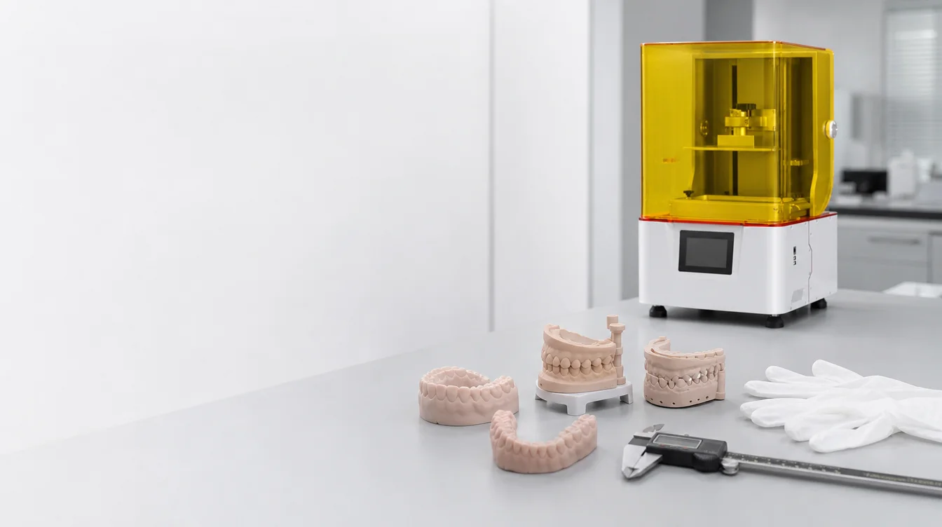
Direct answer
A dental model 3D printing workflow takes a case from scan data to an accepted physical model through eight controlled steps: confirm the model requirement, prepare and check the file, set orientation and supports, print with a validated resin and layer height, wash, dry completely, UV post-cure, and inspect against defined acceptance criteria. Every one of those steps can move dimensions, which is why the last three are part of the process rather than cleanup afterwards. The printer specification tells you the exposure grid and the build volume it can fill; it does not tell you the deviation your models will show. That number comes from measuring your own parts, produced with your own parameters.
Key takeaways
- Write the workflow down before optimising it. Parameters that only exist in an operator's head cannot be audited when a case fails.
- Separate the questions "does it look right" and "does it measure right". They fail at different steps and have different fixes.
- Post-processing is not neutral. Residual uncured resin, trapped solvent and inconsistent UV exposure all shift geometry.
- Resolution is not accuracy. A finer pixel grid changes how small a feature can be represented, not how close the finished model sits to the CAD reference.
- Revalidate when anything upstream changes: resin type, resin batch, layer height, orientation strategy, wash solvent age or curing routine.
Terminology: the words that decide whether a spec is meaningful
Dental model discussions collapse very quickly when two people use "accuracy" to mean different things. The definitions below follow the conventions used in ISO 5725-1 for measurement accuracy and in additive manufacturing terminology, and they are worth agreeing on before comparing any two workflows.
| Term | What it means | Where it gets misused |
|---|---|---|
| Resolution | The smallest addressable step of the imaging or motion system, quoted as a screen resolution or a pixel count. | Quoted as if it were a dimensional guarantee. |
| XY pixel size | The physical size of one pixel projected onto the build plane, in micrometres. | Converted into a tolerance figure. It cannot be. |
| Layer height | The Z increment between exposures, set in the slicer. | Treated as vertical accuracy. It sets the discretisation, not the deviation. |
| Accuracy | The combination of trueness and precision — how close results sit to the reference and how tightly they cluster. | Used as a single number when two are needed. |
| Trueness | Closeness of the mean measured result to the reference value. | Confused with a single good part. |
| Precision | Closeness of agreement between repeated results, independent of the reference. | Used interchangeably with accuracy. |
| Repeatability | Precision under unchanged conditions: same printer, resin, operator, settings, short interval. | Claimed from a single build. |
| Reproducibility | Precision when conditions change: different machine, operator, day or site. | Assumed to equal repeatability. It is usually wider. |
| Tolerance | The permitted range you decide on for a feature, based on how the model is used. | Expected from the supplier instead of defined by the application. |
| Deviation | The measured difference between a part feature and its reference, at a stated location. | Reported as one global figure, hiding local error. |
Resolution is not accuracy. Two systems with identical pixel sizes can produce models with very different deviation, because deviation is also driven by exposure behaviour, resin shrinkage, orientation, support strategy and every post-processing step that follows.
Building a repeatable dental model 3D printing workflow
The eight steps below describe the sequence in the order a case moves through it. The value of writing it out is not that any single step is difficult, but that a model rejected at inspection can be traced back to the step that caused it.
1. Define what the model has to do
An articulated study model, a working model for a thermoformed appliance and a model used to check a restoration's fit are not the same object with different labels. Before anything is sliced, record the intended use, which surfaces are functional, which features are critical, the tolerance you will accept on those features and how the model will be measured. If you cannot state a tolerance, you cannot judge the output later — you can only compare it to the last one.
2. Prepare and check the file
Scan data arrives with the errors of the scanning step already in it, and printing faithfully reproduces them. Check for non-manifold edges, inverted normals, holes and self-intersections. Decide the base design and whether the model is solid, shelled or partially filled — published in-vitro work on dental models has compared different internal structures and base designs and found that these choices measurably affect the finished geometry. Record the choice; do not vary it silently between cases.
3. Set orientation and supports
Orientation determines which surfaces carry supports, where layer stepping falls on curved anatomy, and how large each cross-section is at every height. Occlusal surfaces and other functional areas are normally kept clear of support contact. Support density and tip size are a trade-off: too sparse and the part flexes during separation, too heavy and removal damages the surface. This is a parameter set to be standardised per model type, not a decision made case by case.
4. Print
Resin, layer height and exposure settings should come from the resin's own technical documentation for the printer in use, not from a generic profile. Layer height is a throughput-versus-surface-quality decision within the range the resin and the machine support. Exposure behaviour across the build area matters as well: uneven exposure produces parts whose behaviour depends on where they sat on the platform, which is covered in more depth in the guide on light uniformity across the build area.
5. Wash
Washing removes uncured resin from surfaces and from recesses such as interproximal areas and the intaglio of a model base. Solvent type, agitation, immersion time and solvent condition are all variables. Solvent that has absorbed resin over many cycles cleans less effectively, and prolonged immersion can affect surface dimensions. Follow the resin's technical documentation and track how many builds a given solvent volume has processed.
6. Dry completely
Drying is the step most often skipped, and it is the one that quietly breaks measurements. A model that still holds solvent will behave differently during post-curing and will continue to change afterwards. Complete drying before UV post-curing is a prerequisite, not an optional refinement.
7. UV post-cure
Post-curing advances polymerisation to the state the material was designed to reach. Wavelength, energy, duration, temperature and part placement inside the unit all influence the result, and parts in different positions of a loaded chamber do not necessarily receive the same exposure. Use the routine specified in the resin documentation and keep the loading pattern consistent, otherwise post-curing becomes an uncontrolled source of variation.
8. Inspect and record
Inspection needs a defined method: which features are measured, with what instrument, against which reference, and by whom. Options range from calliper checks on specific distances to full-surface comparison of a scan against the CAD reference. ISO 20896-1 describes a standardised full-arch test object with gauge balls that is widely used in published accuracy studies, which is a useful model for building your own internal reference part. Record results per build; a single measurement tells you about one model, while a series tells you about your process.
Recording template
The table below is a blank template. Fill it with the values your own validation produces — the fields are deliberately empty because no meaningful defaults exist across different resins, geometries and machines.
| Step | Parameter to record | Value | Verified by / date |
|---|---|---|---|
| Requirement | Model type, critical features, accepted tolerance | ||
| File preparation | Repair actions, base design, internal structure | ||
| Orientation | Angle, platform position, support-free surfaces | ||
| Supports | Density, contact tip size, removal method | ||
| Resin and batch, layer height, exposure profile | |||
| Wash | Solvent, time, agitation, cycles on this solvent | ||
| Dry | Method, duration, confirmation of complete drying | ||
| Post-cure | Unit, duration, temperature, loading position | ||
| Inspection | Features measured, instrument, reference, result |
Reading the results
Once a series of models has been measured, the pattern matters more than any individual figure. Two signatures are worth separating.
A systematic shift shows the same deviation, in the same direction, on the same features across every model in the series. That points at something constant in the process: a resin scaling factor, an exposure setting, a post-curing routine, or the reference itself. It is usually correctable once identified.
Wide scatter without a consistent direction points at something varying between builds: solvent condition, drying that is sometimes complete and sometimes not, inconsistent post-cure loading, changing ambient temperature, or a support strategy applied differently by different operators. Scatter is harder to chase, which is why the parameter record exists.
Also separate global from local. A single averaged deviation figure across a whole arch can look acceptable while a specific margin or contact point sits well outside your tolerance. Report deviation where it matters, at the features you named in step 1.
Common mistakes
- Comparing printers on pixel size and build volume, then expecting a tolerance figure to follow from those numbers.
- Treating washing, drying and post-curing as cleanup rather than as process steps with parameters.
- Post-curing parts that are not completely dry.
- Changing resin batch, layer height or orientation without repeating validation.
- Validating on a simple test cube instead of a part with the geometry, wall thickness and features of real cases.
- Judging a model visually and calling the result accuracy.
- Letting each operator apply their own support and orientation preferences.
- Reporting one averaged deviation number and never looking at where the deviation actually sits.
Limits and validation
No workflow description can substitute for measuring your own output. Results depend on equipment condition, resin and batch, temperature, geometry, orientation, supports, exposure, layer height, platform condition, washing, complete drying, UV post-curing and the measurement method used. Published dental accuracy studies report values obtained on specific printers, resins and test objects under laboratory conditions; those figures describe those experiments and are not performance commitments from YIDIMU or from any equipment supplier.
Material handling, exposure settings, washing and post-curing routines should follow the corresponding TDS, SDS and IFU for the resin in use. Where a model forms part of a regulated clinical process, the applicable regulatory and clinical requirements govern, and they sit outside the scope of a printing workflow guide. Throughput planning is a separate question from dimensional validation and is covered in the guide on dental lab 3D printer production capacity.
Relevant YIDIMU systems
Eternal Y8
A 10.3-inch 8K masked vat photopolymerization system. Note the terminology point: masked exposure systems of this type are often described loosely as "SLA", but they cure each layer by projecting a full-area mask image rather than by tracing a path with a laser, which is what laser SLA does. The published specifications are:
- Screen: 10.3-inch, 7680 × 4320
- XY pixel size: 29.7 μm
- Build volume: 228 × 128 × 235 mm
- Layer thickness: 0.025–0.1 mm
- Print speed: up to 60 mm/h (Z-axis)
- Resin wavelength: 405 nm UV
- Supported formats: STL / OBJ
- Machine dimensions: 350 × 330 × 600 mm
These are equipment specifications. They describe the exposure grid, the build envelope and the layer range available to you; they are not accuracy, repeatability or tolerance figures, and no such figures can be derived from them. Full details are on the Eternal Y8 dental resin 3D printer page, alongside the wider dental resin 3D printer range.

Material selection sits alongside equipment selection: review the YIDIMU photopolymer resin range and confirm suitability against the resin documentation and a representative sample test rather than a category name. Broader context on model, orthodontic and guide-related work is collected under dental 3D printing applications.
Workflow checklist
- Intended use, critical features and accepted tolerance written down before slicing
- File checked for holes, inverted normals and self-intersections
- Base design and internal structure standardised per model type
- Orientation and support strategy documented, not improvised
- Resin, batch, layer height and exposure profile recorded for the build
- Wash solvent, time and cycle count tracked
- Complete drying confirmed before post-curing
- Post-cure routine and loading position kept consistent
- Measurement method, reference and features defined in advance
- Results logged per build so trends are visible over a series
- Revalidation triggered by any change to resin, batch, parameters or routine
FAQ
Is a dental model workflow different from a general resin printing workflow?
The sequence is the same, but the tolerance expectations, the features that matter and the documentation requirements are stricter. Dental models are frequently used as the basis for something else — an appliance, a check of fit, a record — so deviation propagates. That justifies tighter parameter control and more formal inspection than a visual prototype needs.
Does a smaller XY pixel size give a more accurate model?
Not by itself. Pixel size affects how finely a feature edge can be represented in the exposure image. Measured deviation also depends on exposure behaviour, resin characteristics, geometry, orientation, supports and all three post-processing steps. Two machines with the same pixel size can produce noticeably different results, and the same machine will produce different results with different resins.
Should dental models be printed hollow or solid?
It depends on what the model is for and how it will be handled. Published in-vitro studies have compared shelled, partially filled and fully filled dental models and reported differences in the resulting geometry, so the choice is not neutral. Decide it per model type, validate it with your own resin and printer, then apply it consistently.
How long should models be washed and post-cured?
Use the times in the technical documentation for the specific resin, then confirm them on your own parts. Times are not transferable between resins, and a routine that works for one material can under-cure or over-expose another. Solvent condition and post-curing unit loading both shift the effective result even when the stated times are unchanged.
Do I need to revalidate when the resin batch changes?
Check a representative part rather than assuming continuity. Batch is one of the variables that can shift results, which is why it belongs in the parameter record. If your inspection log shows the same features drifting after a batch change, you have a traceable cause instead of an unexplained problem.
Is masked vat photopolymerization the same as SLA?
They are related but not identical. Laser SLA traces each layer with a focused laser spot. Masked systems such as the Eternal Y8 expose a full-area image through a mask, curing the whole cross-section at once. Both are vat photopolymerization, and both need the same washing, drying and post-curing discipline, but the exposure mechanism differs and the terms should not be used interchangeably.
Discuss your dental model application
If you are evaluating a dental model 3D printing workflow for your lab, the most useful starting point is a real case rather than a specification comparison. Share the CAD or STL file, model dimensions, the application, the critical features and where they sit, the tolerance you need to hold, the material category you are considering, expected quantities, and your surface finish and inspection requirements. With that information the equipment, resin and post-processing sequence can be reviewed against what your models actually have to do.