
Count only parts that fit with the approved orientation, spacing, supports and resin workflow.
Dental Production Planning
Dental Lab 3D Printer Production Capacity: A Practical Planning Guide
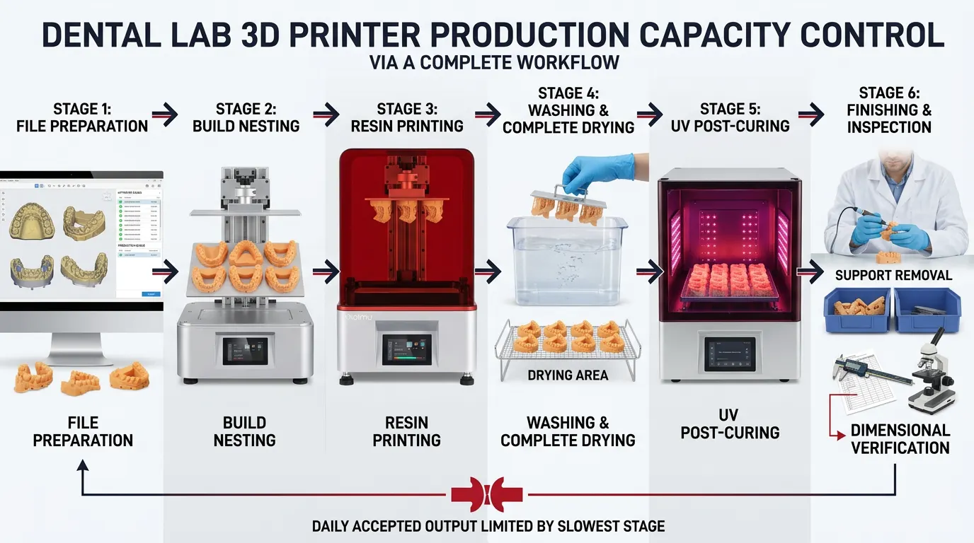
Production capacity is the number of acceptable dental cases a lab can complete through printing, washing, drying, UV post-curing, finishing and inspection within a defined shift or day.
Direct Answer
How should dental lab 3D printer production capacity be calculated?
Dental lab 3D printer production capacity should be calculated from accepted cases per shift or day, not from nominal Z-axis speed. Start with the number of validated parts that fit in one build, then include oriented build height, exposure and movement time, preparation and changeover, washing, complete drying, UV post-curing, support removal, inspection, staffing, maintenance and first-pass yield.
The practical output of the laboratory is controlled by its slowest stage. A printer that completes many models is not a high-capacity system when the wash station, curing chamber, operator or quality-control step cannot process the same volume.
Measure the Right Output
Production capacity is a workflow result, not a printer specification
A useful capacity figure must answer a defined operational question: how many orthodontic models, removable-die models, implant models, surgical-guide-related parts, trays, splints or other approved parts can the laboratory deliver to its acceptance standard during a normal production period?
Three numbers are often confused. Build capacity is how many parts can be arranged in one print job. Printer throughput is how many builds or printed parts the equipment can complete in a period. Lab throughput is how many acceptable cases pass the complete digital and physical workflow. The third number is usually the one that matters for staffing, delivery commitments and equipment purchasing.
Use cases as well as parts
One dental case may contain an upper model, a lower model, dies, a gingival mask or other components. Record parts per build for machine scheduling, but convert that output into accepted cases before comparing the system with daily demand.
Include file release, setup, printing, drainage, unloading, cleaning and changeover—not print time alone.
Compare the printer with wash, drying, curing, finishing and inspection capacity over the same period.
Use the percentage of parts accepted after the complete process, measured over repeated representative builds.
Capacity Model
Build a capacity calculation in six stages
Use the same representative files, resin, acceptance criteria and shift length for every system being compared. Changing the model mix or quality target makes the capacity comparison unreliable.
Define the case mix
List the expected daily volume by part type. Separate models, guides, trays, splints, temporary applications and other workflows because they may use different resins, orientations and post-processing procedures.
Validate parts per build
Arrange actual production files on the usable platform. Keep required spacing, drainage, labels and support access. Do not estimate capacity by dividing platform area by a model footprint.
Measure the full print cycle
Record preparation, file transfer, resin checks, printing, drainage, platform removal, part removal and reset. For layer-based vat photopolymerization, the highest oriented part can strongly influence the layer count.
Match downstream capacity
Calculate wash loads, drying positions, curing loads and required cycle times using the current resin documentation and validated process. Mixed materials may require separate handling.
Account for operator touch time
Include setup, unloading, support removal, labeling, cleaning, inspection, documentation and maintenance. A cycle may run unattended, but it is not labor-free.
Convert output into accepted cases
Apply a measured first-pass yield and track reasons for rejection. Reprints consume printer time and downstream capacity while delaying the original case.
Nesting and Orientation
More parts per build can increase capacity—but may increase build height
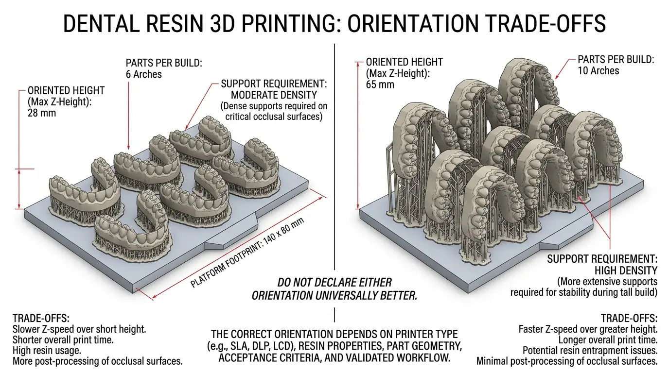
Orientation is a production tradeoff. A lower, more horizontal layout may reduce the total number of layers and shorten a job for certain dental models. A steeper layout can reduce the platform footprint and allow more models in one batch, but it may increase build height, supports and print duration.
Published dental research has found that orientation and layer thickness can affect accuracy, time and material consumption. A 2024 systematic review also noted that horizontal printing can be efficient for single-model production, while more vertical placement may accommodate more models for large or overnight batches. These findings should guide testing, not replace printer- and resin-specific validation.
- Compare accepted models per hour, not only models per platform.
- Protect critical margins, contacts and fitting surfaces from unnecessary supports.
- Check drainage and resin flow around dense batches.
- Use the same orientation in repeatability and capacity trials.
Planning Worksheet
Record these inputs for every representative dental part
A capacity forecast becomes more reliable when every supplier or printer is tested with the same worksheet. Replace assumptions with measured values after trial builds.
| Input | What to record | Why it changes capacity |
|---|---|---|
| Part and case type | Parts per case, daily demand, priority and delivery window | Different workflows use different materials, settings and post-processing steps. |
| Validated nesting | Accepted parts per build with approved spacing and supports | Nominal platform dimensions do not show the usable production layout. |
| Oriented height | Highest supported Z dimension in the actual build | Layer count and movement cycles are linked to the tallest oriented part. |
| Printer cycle | Preparation, print, drainage, unloading and changeover time | Non-printing machine time reduces the number of builds available per shift. |
| Wash and drying | Parts per load, wash stages, handling and complete drying time | Incomplete or overloaded post-processing can create defects and rework. |
| UV post-curing | Validated load, positioning and cycle for the selected material | The curing chamber can become the bottleneck when printer output increases. |
| Finishing and inspection | Support removal, surface work, labeling, scanning or dimensional checks | Manual work often determines the sustainable rate during peak demand. |
| First-pass yield | Accepted parts divided by all parts started over repeated builds | Scheduled output is not deliverable output when failures and reprints are ignored. |
A simple planning equation
Printer accepted output per shift = validated parts per build × completed builds per shift × measured first-pass yield.
Then compare this number with the accepted output capacity of washing, drying, curing, finishing and inspection. The lowest sustainable value is the current production bottleneck.
Common Bottlenecks
Why adding a faster printer may not increase accepted output
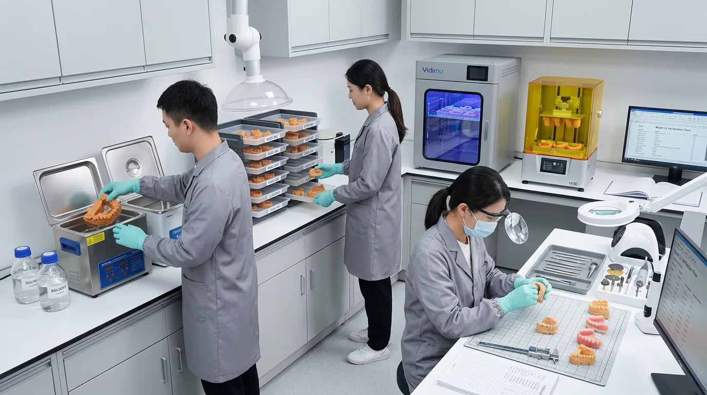
Dental labs often discover that the printer is not the limiting resource. A single wash container, insufficient drying space, a small curing chamber, resin changeovers or one trained operator can cap the number of cases that reach inspection.
Capacity can also fall when the lab mixes many urgent cases into partially filled jobs, prints multiple materials with frequent vat changes, delays file approval, or lacks a clear queue for unloading and post-processing. These are scheduling and workflow problems rather than isolated hardware problems.
- File bottleneck: scans, model design or approval arrive too late to fill planned batches.
- Printer bottleneck: validated demand exceeds available build cycles.
- Material bottleneck: changeovers, filtration or storage control interrupt the schedule.
- Post-processing bottleneck: washing, drying or curing cannot accept each completed batch.
- Labor bottleneck: unloading, finishing and inspection accumulate during shift changes.
- Quality bottleneck: reprints and corrective work consume capacity reserved for new cases.
Equipment Evaluation
How to compare dental 3D printers for production capacity
Start with the models and delivery schedule, then test the equipment as part of a complete production cell. Build volume, layer settings and nominal speed are screening specifications. They do not independently prove repeatability, usable nesting density or accepted cases per day.
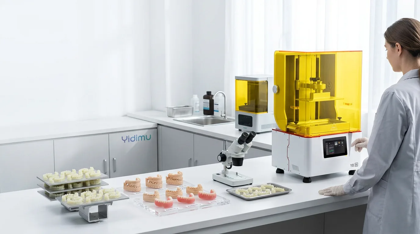
The current YIDIMU Eternal Y8 product page lists a 228 × 128 × 235 mm build volume, masked vat photopolymerization, a 0.025–0.1 mm layer range and a stated Z-axis speed of up to 60 mm/h. These specifications help define the machine envelope, but actual dental-lab capacity still depends on the model geometry, orientation, resin, validated settings, loading pattern and post-processing workflow.
Before selecting equipment, ask the supplier to process representative files with the proposed printer, resin and post-processing method. Review more than one build when repeatability matters. The evaluation should document the number of accepted parts per build, total elapsed time, operator touch time, cleaning and curing load, dimensional or fit checks, observed failure modes and maintenance requirements.
Do not compare printers with different acceptance standards
A high count is not meaningful when the parts are not suitable for the intended dental workflow. Define measurable acceptance criteria before the trial and verify the current technical documentation, material intended use and local regulatory requirements for any patient-contact or clinical application.
YIDIMU provides dental 3D printer options, resin materials, post-processing equipment and application discussion. Product suitability and final results should be confirmed through representative sample testing and the current documentation for the selected printer and material.
Scaling Strategy
Scale the production cell in the order of the bottleneck
Production planning research in additive manufacturing treats nesting and scheduling as connected problems because multiple parts share limited build space and machine time. Dental labs can apply the same principle with a practical sequence.
Stabilize the process
Lock the approved file preparation, orientation, supports, resin, settings, washing, drying, curing and inspection method for each part family.
Measure the bottleneck
Track queue time and accepted output at every stage for several normal production days, not only during a demonstration build.
Improve scheduling
Group compatible files, reserve capacity for urgent cases and coordinate printer completion with available wash, dry and cure slots.
Add parallel capacity
Add another printer, wash station, curing unit or trained operator only where measured demand exceeds sustainable output.
Protect maintenance time
Schedule cleaning, platform and vat inspection, calibration checks and consumable replacement instead of assuming every hour is productive.
Recalculate after changes
A new resin, model type, orientation, shift pattern or acceptance requirement creates a new capacity model that must be validated again.
Frequently Asked Questions
Dental lab 3D printer production capacity FAQ
How many dental models can one 3D printer produce per day?
There is no universal number. Daily accepted output depends on models per build, oriented build height, exposure and motion settings, changeover time, available shifts, post-processing capacity, staffing and first-pass yield. Calculate capacity with representative files and validated resin settings rather than a nominal speed alone.
Does a larger build platform always increase dental lab capacity?
A larger platform can increase parts per build, but only when the lab can nest the required models without compromising orientation, supports, resin flow or quality. Capacity will not improve if washing, drying, curing, finishing or inspection is already the bottleneck.
Is vertical or horizontal orientation better for production?
The best orientation depends on the application. Horizontal layouts may reduce height and print time for some models, while more vertical layouts can fit more models on a platform. Orientation also affects supports, material use, surface condition and dimensional behavior, so the lab should validate the complete workflow.
Should a dental lab calculate capacity in parts or cases?
Both are useful, but accepted cases are usually the better business metric because one case may require several models or components. Track parts per build for machine planning and accepted cases per shift or day for delivery planning.
How should failed prints be included in capacity planning?
Use a measured first-pass yield from repeated representative builds. Capacity should be based on accepted parts after printing, washing, drying, curing, finishing and inspection, not on the number of parts sent to the printer.
Technical References
Sources used for the capacity framework
- NIST: Nesting and Scheduling Problems for Additive Manufacturing
- Effect of build angle and layer height on the accuracy of 3D-printed dental models
- Systematic review of printing orientation, accuracy, cost and time efficiency for dental models
- Effect of orientation and layer thickness on accuracy, printing time and material consumption of printed denture bases
- YIDIMU Eternal Y8 current product information
Validate Before You Scale
Submit representative dental files for a production-capacity review
Share the part types, model dimensions, daily case mix, material requirements, current workflow, shift pattern and acceptance criteria. YIDIMU can discuss printer selection, build layout, resin and post-processing requirements based on the information provided.