
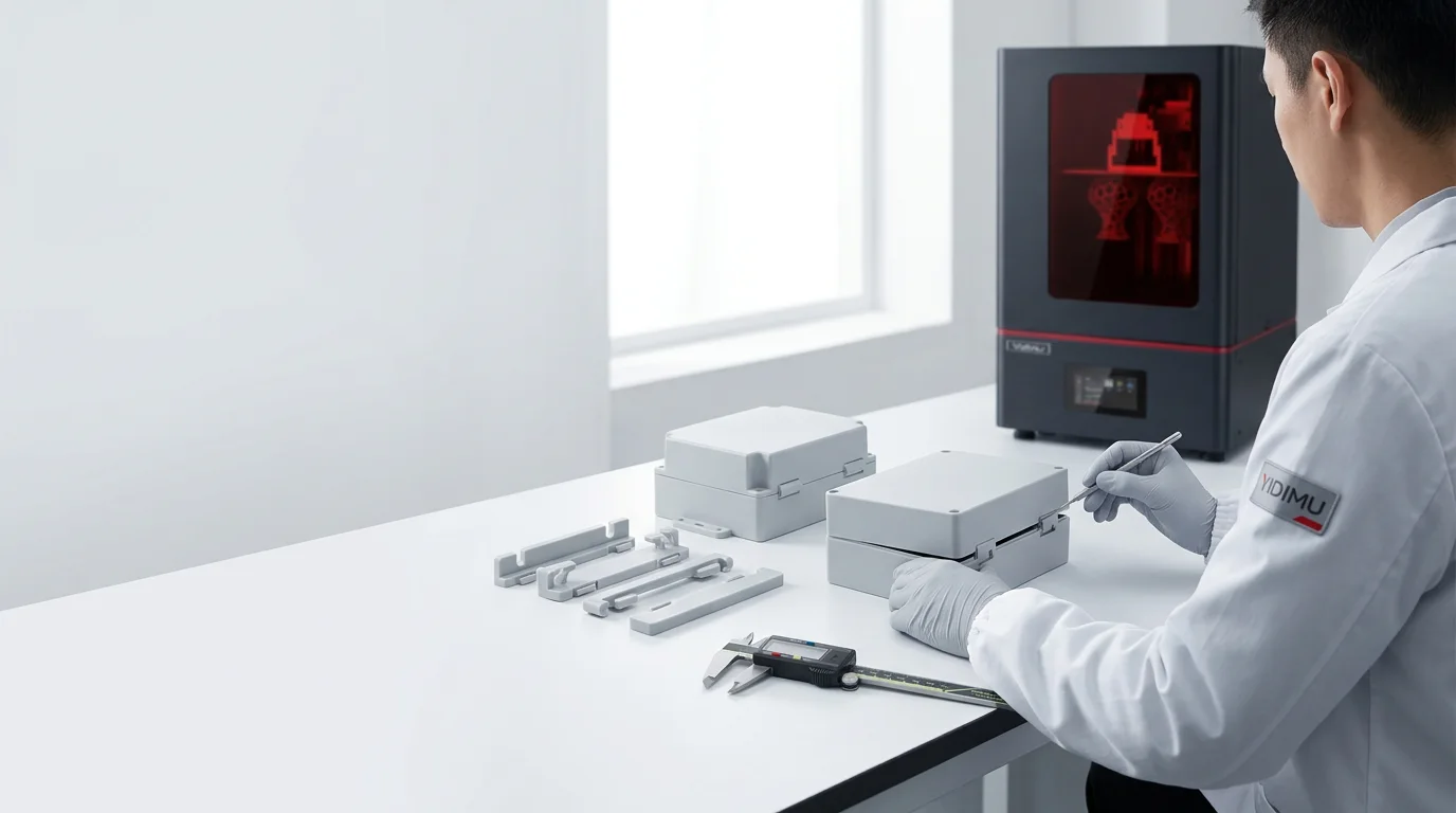
Direct answer
Prototype snap fit validation with resin printing is most useful when the printed parts are treated as a controlled comparison set. Keep the mating geometry, print orientation, support strategy, washing, complete drying, UV post-curing and inspection method consistent; then change one design variable at a time. Evaluate insertion force, full engagement, retention, release, visible whitening or cracking, interference with nearby features and the effect of repeated cycles. A resin prototype can reveal geometry and assembly problems early, but it does not automatically reproduce the long-term behavior of an injection-molded production polymer. Final decisions should therefore include representative material and production-process validation.
Key takeaways
What a useful snap-fit prototype must prove
Confirm hook engagement, clearance, lead-in, stop surfaces and assembly access before judging subjective “click” quality.
Change hook height, beam length, root transition or mating clearance independently so the result remains interpretable.
Different orientation, support scars, incomplete drying or uneven post-curing can change how nominally identical parts behave.
Record force, displacement, engagement, damage location and cycle count rather than relying only on hand feel.
Nearby walls, ribs, seals, cables and fasteners can prevent correct deflection even when the snap feature looks valid alone.
Use resin printing to screen design options, then validate the chosen design in the intended production material and process.
Start with the test question
Define what “works” before printing
A snap fit is not successful merely because two parts can be pushed together. The joint must perform a specific task: permanent retention, serviceable closure, alignment, tamper resistance, component positioning or a combination of these. The validation plan should translate that task into observable checks.
For a serviceable enclosure, the important questions may be: Can an operator assemble it without damaging the hook? Does the latch fully engage? Is the retention force adequate during handling? Can the housing be opened with the intended tool? Do neighboring ribs block beam deflection? For a one-time assembly, release behavior may be irrelevant while insertion damage and final retention become more important.
When the design is part of a larger engineering prototype, review the broader factory prototyping and product-development workflow so the latch test is connected to dimensional inspection, assembly sequence and downstream evaluation.
Geometry controls
Snap-fit features to vary deliberately
Most prototype programs become difficult to interpret when several dimensions are changed at once. A more reliable method is to create a small matrix in which each version changes one primary variable while the rest of the part remains identical.
| Design variable | What it influences | What to inspect | Common interpretation risk |
|---|---|---|---|
| Beam length and thickness | Deflection behavior and local stress | Root condition, recovery, permanent set and cracking | A stiff result may come from geometry, material state or print orientation |
| Hook height and undercut | Engagement and retention | Full seating, release path and damage to mating edge | More undercut can increase retention but also make assembly destructive |
| Lead-in angle | Insertion path and peak force | Smooth entry, scraping and part misalignment | A good lead-in cannot compensate for insufficient beam travel |
| Root radius or transition | Stress concentration | Whitening, cracks and repeat-cycle failure at the beam root | Support marks near the root can obscure the real failure mode |
| Mating clearance | Assembly tolerance and rattle | Interference, incomplete engagement and looseness | Printed dimensional bias can be mistaken for a CAD clearance problem |
| Stop and locator surfaces | Final position and load path | Whether the snap carries unintended structural load | The latch may appear weak when the real issue is missing hard stops |
Use version identifiers on a non-critical surface or maintain a separate build map. The identifier should not modify the flexible beam, mating edge or any surface used for measurement.
Prototype snap fit validation with resin printing
Control the print and post-processing variables
Orientation and support placement
Orientation can affect surface quality, support access, dimensional behavior and the direction in which a thin snap beam is formed. The objective is not to find a universally correct angle; it is to choose an orientation that protects the critical hook, root and mating surfaces while remaining repeatable across all variants.
Avoid placing support contact points on the hook face, lead-in surface, beam root, measurement datum or the mating edge that determines engagement. When support contact cannot be avoided, document its location and use the same arrangement for every version so the comparison remains meaningful.
Washing, complete drying and UV post-curing
Printed parts should be washed according to the applicable material instructions, completely dried and then UV post-cured using the documented workflow for that resin. Residual liquid, incomplete drying or inconsistent post-curing can alter surface condition and mechanical response. Do not compare parts processed with different uncontrolled procedures.
Material handling, cleaning and post-curing must follow the corresponding TDS, SDS, IFU or other formal technical documents. Do not transfer a time, solvent or curing condition from one resin to another without documented confirmation. YIDIMU lists photopolymer resin options and post-processing equipment, but project suitability still requires compatibility review and representative testing.
Conditioning before measurement
Measure and test all versions at a consistent point after post-processing. Record the date, processing route and environmental conditions used by the project team. This does not make the resin identical to the production polymer; it reduces avoidable variation inside the prototype comparison.
Controlled workflow
A practical seven-step validation sequence
Set the assembly requirement
Define whether the joint is permanent or serviceable, the assembly direction, access limitations, visible surfaces, expected handling and the pass/fail observations.
Inspect the CAD load path
Confirm that the beam has room to deflect, the hook can clear the mating edge, hard stops carry structural load and nearby ribs or walls do not block motion.
Create a controlled variant set
Choose a baseline and vary one geometry factor at a time. Keep the rest of the assembly, print setup and test method unchanged.
Plan orientation and supports
Protect the functional surfaces and document the build arrangement. Use the same orientation logic for the full comparison set.
Post-process consistently
Wash, completely dry, UV post-cure and remove supports in accordance with the selected material's formal instructions.
Inspect before assembly
Check hook geometry, beam root, contact scars, warpage, debris and mating dimensions. Reject visibly damaged specimens before drawing conclusions from the assembly test.
Test, record and escalate
Measure the defined force or displacement where possible, record failure location and cycle history, then move the preferred geometry into production-material and process validation.
Inspection and evidence
Record more than “too tight” or “too loose”
Subjective feedback is useful, but it should be connected to repeatable observations. A simple fixture, force gauge or controlled insertion method can separate operator technique from design behavior. The exact equipment depends on the project; the important point is to use the same method for every variant.
| Evidence | How to capture it | Why it matters |
|---|---|---|
| Insertion behavior | Force-displacement record, controlled manual fixture or documented operator method | Shows whether the lead-in and beam travel produce a stable assembly path |
| Full engagement | Visual check, sectioned sample, gauge feature or measured final position | Prevents a false pass where the parts appear closed but the hook is not seated |
| Retention or release | Defined pull, pry or service-tool procedure | Connects the joint design to the actual product requirement |
| Damage location | Macro photographs and marked specimen map | Distinguishes beam-root stress, hook damage, mating-edge damage and support-related defects |
| Cycle response | Repeat the same assembly/disassembly sequence and inspect after each interval | Reveals permanent set, progressive cracking or loss of engagement |
| Dimensional condition | Measure critical datums and gaps with a documented method | Separates CAD geometry issues from print or post-processing variation |
Do not report a single successful part as proof of production capability. Use enough specimens and builds to answer the project's risk question, then define a separate plan for production-process validation.
Failure interpretation
Common prototype results and what to check next
The hook will not pass the mating edge
Check available beam travel, lead-in geometry, interference, print debris, support scars and the real assembly direction. Increasing force without understanding the blockage can damage the hook or mating part.
The parts close, but the latch does not retain
Verify full seating, hook engagement, undercut, hard-stop position and whether the beam remains deflected after assembly. A joint can look closed while the hook never reaches its intended position.
The beam cracks near the root
Inspect the root transition, abrupt thickness changes, support contact, print orientation and post-processing consistency. Also question whether the selected prototype material can represent the intended deformation mode.
Nominally identical samples behave differently
Compare build position, orientation, support removal, cleaning, complete drying, UV post-curing, storage and measurement timing. Variation can come from the prototype process as well as the geometry.
The snap feels good by hand but fails in the complete product
Recreate the real assembly access, surrounding components, gasket compression, cable routing, fastening sequence and enclosure stiffness. The isolated snap feature may not represent the system-level load path.
Relevant YIDIMU systems
Industrial resin printing for engineering comparison parts
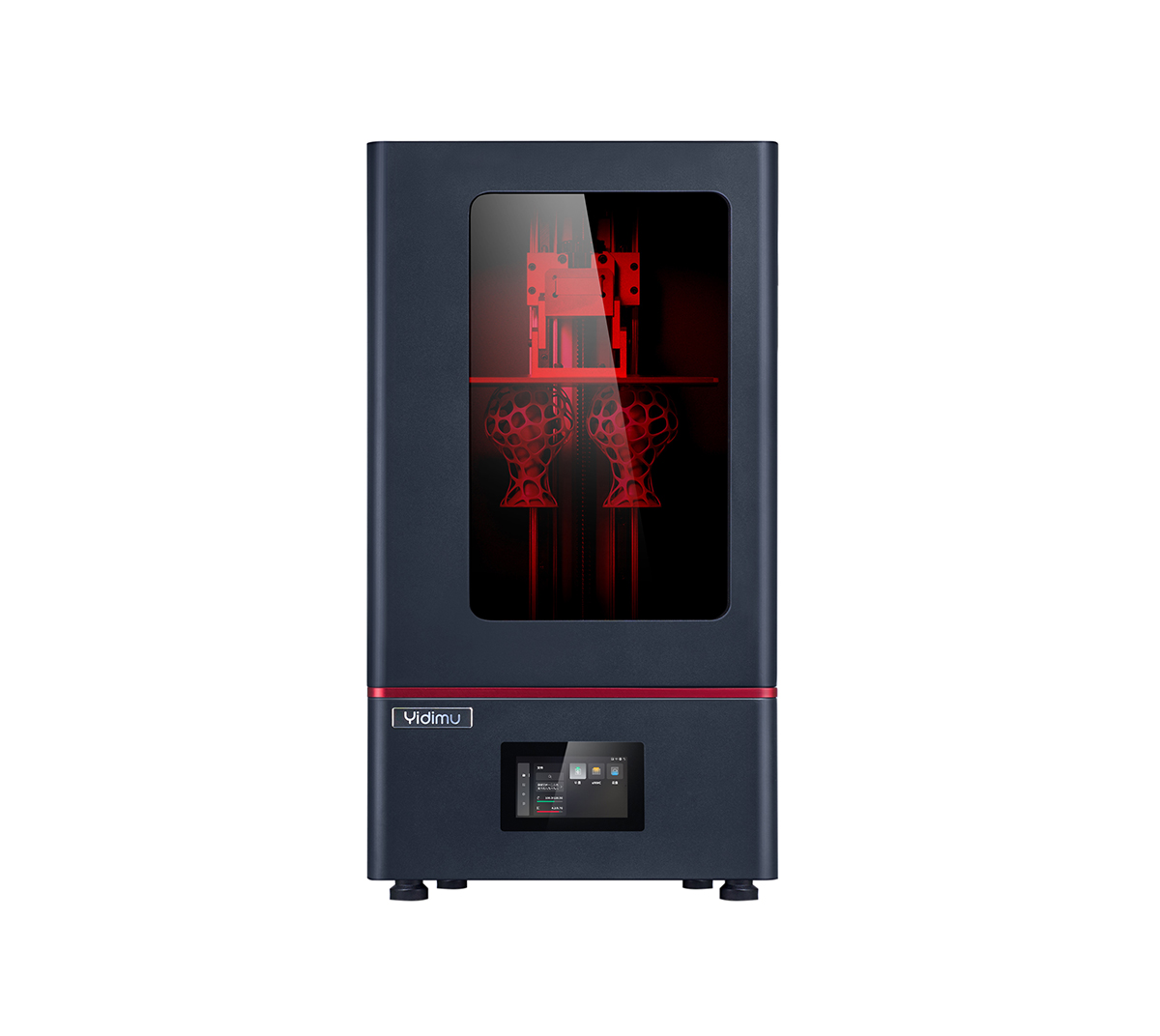
Eternal M1 and Eternal M2
For snap-fit work, the relevant question is not which machine has a claimed universal accuracy figure. It is whether the selected system, resin, orientation and post-processing workflow can reproduce the critical geometry of the representative assembly with sufficient consistency for the planned comparison.
Eternal M1 is positioned for industrial prototypes and engineering models. Eternal M2 can be considered when the evaluation involves larger assemblies, reduced part splitting, multi-part layouts or broader prototype sets. Final suitability should be confirmed from the model, overall dimensions, critical features, material requirement, quantity and inspection plan.
Practical evaluation checklist
Information to prepare before sample validation
- Complete STL or OBJ files for both mating parts
- Overall part and assembly dimensions
- Intended function: permanent or serviceable joint
- Critical hook, beam, gap and datum dimensions
- Assembly direction and available access
- Nearby ribs, seals, cables, fasteners and hard stops
- Prototype material behavior required from the test
- Planned production material and manufacturing process
- Quantity of variants and specimens per condition
- Surface, cosmetic and support-contact restrictions
- Insertion, retention, release or cycle test method
- Acceptance criteria and measurement records
Limitations and validation
Why a printed snap-fit pass is not the final production approval
Resin printing can shorten the loop between CAD changes and physical assembly evidence. It is especially useful for identifying blocked deflection, poor lead-ins, incorrect undercuts, inaccessible release paths, interference, weak locators and unsuitable assembly sequences. However, the prototype resin may differ from the intended production polymer in stiffness, elongation, creep, fatigue, environmental response and molded-feature behavior.
Use the printed result to eliminate weak concepts and narrow the design window. The selected geometry should then be validated using representative production material, tooling conditions, part orientation, conditioning, assembly equipment and inspection methods. A parameter table or a successful demonstration sample cannot replace this project-specific step.
FAQ
Prototype snap-fit validation questions
Can a resin-printed snap fit be used for repeated opening and closing?
It can be tested for repeated cycles when that behavior is part of the requirement, but the result applies to the specific resin, geometry, print setup and post-processing condition. It should not be assumed to predict the fatigue life of a different production polymer.
Should the snap beam be printed in the same orientation as the final product?
Not necessarily. The final molded orientation and the print build orientation are different process concepts. Choose a print orientation that protects the critical surfaces and supports a repeatable comparison, then document that choice.
How many geometry variants should be printed?
Use the smallest controlled set that can answer the design question. A baseline plus several single-variable changes is usually more informative than many versions that alter several dimensions at once.
Can one successful assembly confirm the tolerance?
No. One part can show that assembly is possible, but it does not establish process capability, dimensional distribution or production yield. The sample count should match the risk and decision being made.
Which resin should be used for snap-fit prototyping?
Select material behavior based on the test objective and confirm compatibility with the printer and post-processing workflow. Follow the relevant TDS, SDS and IFU. Do not infer suitability from a generic resin name alone.
What files and information should be sent for YIDIMU project review?
Provide the model files, overall dimensions, mating geometry, intended use, material requirement, quantity, surface restrictions, critical fit concerns and the inspection or assembly method you plan to use.
Project review
Apply the validation plan to your snap-fit assembly
Send both mating models, overall dimensions, critical hook and clearance dimensions, intended assembly behavior, material requirement, variant quantity, surface restrictions and the force, fit or cycle checks that matter to the project. YIDIMU can use this information to discuss printer, resin and post-processing options for representative sample evaluation without assuming a guaranteed result or fixed delivery outcome.
Submit model and project requirements →